Building the gingery metal mill

Home enthusiasts discuss their Foundry & Casting work.

Moderator: Harold_V

norman
Posts: 50
Joined: Tue May 18, 2010 5:16 pm

Re: Building the gingery metal mill

Post by norman »

I now have the mills spindle shaft in place and I've bored the spindle shaft to 3/8" Id for a draw bar or for knocking out a stuck bit.
I'm now starting on the drive train for the mill. I'm still looking for a suitable electric motor for this so until I find one I'll be using the shaper's motor.
boring the spindle id to 3/8" using the shaper's motor and drive system
Image
I swapped ends on the spindle and finished boring the through hole from the other end. the shaft is 8" long my longest drill bit is about 6" long.
Image
this is how I pinned the bearing in the spindle head its done same as a type 1 vw engine block main bearing.The plans call for slitting the bearing and the slight crush of the housing holding the bearings in place.
Image
Gadget
Posts: 61
Joined: Thu Dec 24, 2009 9:02 pm
Location: Michigan

Re: Building the gingery metal mill

Post by Gadget »

Very nice work Norman. I need to get going on mine again, summer has been so busy for me.
Dan
norman
Posts: 50
Joined: Tue May 18, 2010 5:16 pm

Re: Building the gingery metal mill

Post by norman »

Gadget
I hope you get back to building soon.
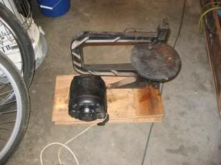
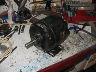
I found a motor today at a flea market it was mounted on an old jig saw the motor is a heavy old iron frame 1725 rpm 1/4 h.p(just what I was looking for!). it has the spring cap oilers on it so I'll try to mount it with the oil holes facing up which will require the frame for the motor assembly to be made a little different than what the plans call for. The jig saw is a cast iron frame and its been broken and welded so I might try to get it up and running. My friend gave me a 1/4 hp motor 1050 rpm that I will try on the saw.
I paid $25.00 for the saw and motor, really only wanted the motor.

this is the motor and saw
Image
this is the motor heavy old iron
Image

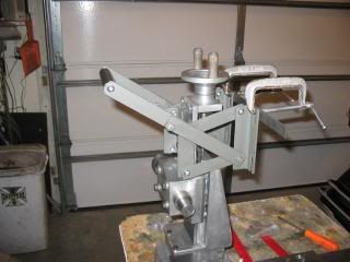
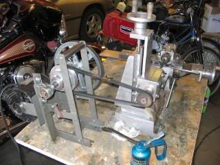
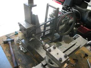
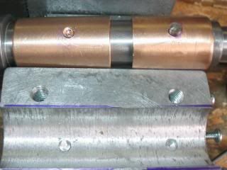
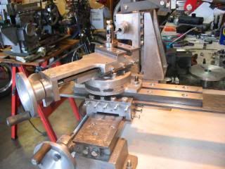
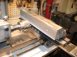
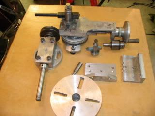
the start of the transmission.
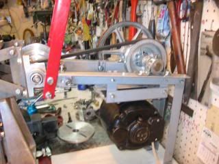
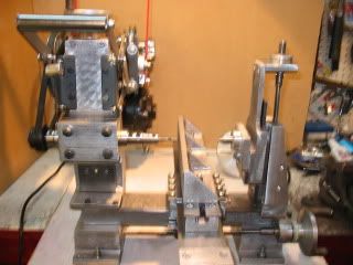
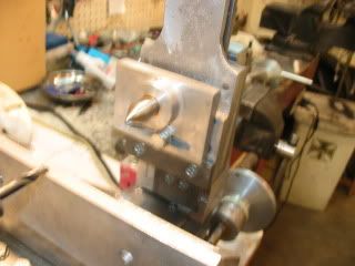
first photo is the position to tighten the belt between the spindle and the second jack shaft which is being built and will go where the "C" clamps are now. the bearing blocks are cast and in the process of being machined.
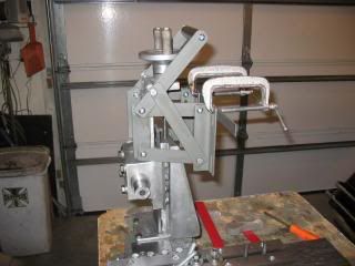
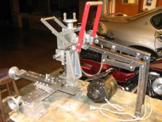
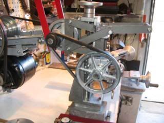
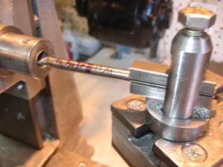
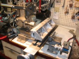
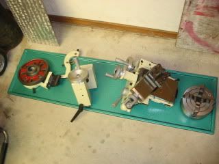
last photo it is in the released position. very simple, I did drill some extra holes due to measurement errors. The plans call for the assembly to be riveted together instead of that I bolted it together
good thing as I put it together wrong a couple of times. I used 1" wide strap instead of the 3/4"wide strap called for in the plans the place where I buy the steel doesn't have the strap in 3/4" width.
Image

Image
Last edited by norman on Sat Sep 11, 2010 11:52 am, edited 1 time in total.
Gadget
Posts: 61
Joined: Thu Dec 24, 2009 9:02 pm
Location: Michigan

Re: Building the gingery metal mill

Post by Gadget »

Norman,
I have a 2hp treadmill motor I plan on using. I can then have an almost infinite range of speeds for the mill. I probably will not use the step pulleys in the plans but will use the countershaft to gear it down a bit. I'm at the point now where I have to get the motor and countershaft mounted to bore the spindle. I just have to find the time to do it.
I look forward to seeing your setup when you get the motor mounted.
Dan
norman
Posts: 50
Joined: Tue May 18, 2010 5:16 pm

Re: Building the gingery metal mill

Post by norman »

I took the electric motor apart to change it's mounting pad so I can mount it up side down and have the oilers facing up. When I took it apart the wire leads were brittle and the insulation fell off so I rewired the leads to the windings and to the wiring plate. retied the wires with bee's wax lased cotton cord plus switched the motor's rotation.
I finished up building the mill's transmission then took it apart and painted it. I'll post photos once I get it back together again. I made the frame very close to the plans so there isn't nothing exciting to say about building the frame for the transmission. I used 1/4" bolts where the plans called for 3/16" rivets, again used 1" strap where the plans called for 3/4".
norman
Posts: 50
Joined: Tue May 18, 2010 5:16 pm

Re: Building the gingery metal mill

Post by norman »

I've made a face plate for the mill and used it to machine the compound parts for the mill. So far the mill seems to work fine, it could use a larger hp motor as the 1/4 hp motor struggles to start when using the higher speeds on the transmission, so I disengage the back belt when starting. I jury rigged a tool holder for the quill and got the compound finished. I'm now making the tool holder so soon I'll be boring the spindle to hold milling tools.
start of the transmission for the mill
Image
side view of the mill with the completed transmission.
Image
other side view
Image
the compound
Image
Last edited by norman on Thu Sep 23, 2010 10:56 pm, edited 1 time in total.
norman
Posts: 50
Joined: Tue May 18, 2010 5:16 pm

Re: Building the gingery metal mill

Post by norman »

Made the tool holder and the boring bar tool holder today. This evening I bored the spindle head to 0.625 and drilled and tapped the spindle head for 5/16" fine thread set screws. Now its on to making the face mill, back to pattern making and doing some casting.

start of boring the spindle head
Image
Tada!! done.
Image
the shaper cutting the flat area on the shaft for the face mill sure beats hand filing. Photo is an action shot while the shaper is running.
Image
norman
Posts: 50
Joined: Tue May 18, 2010 5:16 pm

Re: Building the gingery metal mill

Post by norman »

I finally completed my mill project last night. I do have one more hand wheel to cast to finish the mill. My lap top computer crashed about a month ago so updating my progress came to a halt.
I've made the permanent table ,and the tail stand and other parts. Operating this mill is the first
metal mill I've ever tried to operate so it been a real learning experience. There is still things I want to do different now that the mill is done so I plan on changing some things on the mill. One is it could use more hp the 1/4 hp motor is a little weak so if I can find a 1/2 hp that might be a better choice. I also want to redo the graduations on the hand wheels so they will be adjustable, right now they are just glued on tape measuring strips in millimeters.
I have the book on deluxe accessories so I plan on making the 4 jaw chuck for the mill and the dividing head plus some of the other goodies in the book.
I'll get some photos up of the mill soon. Thanks for all of your interest on my project.
Gadjet you need to get a crackin on your mill!
Norman
Gadget
Posts: 61
Joined: Thu Dec 24, 2009 9:02 pm
Location: Michigan

Re: Building the gingery metal mill

Post by Gadget »

Norman,
I've actually done some of the transmission work. Right now I am trying to decide if I want to use the treadmill motor or go with a normal motor. I'm probably going to try to make all pulleys myself to save some bucks. The work I've done recently doesn't look like much so I haven't posted. I have been chipping away at it though.
Dan
User avatar
ken572
Posts: 2600
Joined: Sun Mar 14, 2010 8:11 pm
Location: Mesa, Arizona. 85201-1517

Re: Building the gingery metal mill

Post by ken572 »

norman.

Very nice workmanship on all of your work shown. :wink:

Ken.
One must remember.
The best learning experiences come
from working with the older Masters.
Ken.
norman
Posts: 50
Joined: Tue May 18, 2010 5:16 pm

Re: Building the gingery metal mill

Post by norman »

Thanks Ken for the kind words!!
The Mill completed. Minus the hand wheel for the tail stand.
Image
machining the permanent cross slide base using my home made fly cutter
Image

Image

Image
there it is. I made the last hand wheel yesterday cast and machined but no pictures of that.
I put up the wood background so it will be a little easier to see in the photo sort of covers up the clutter.
Last edited by norman on Mon Nov 08, 2010 1:19 pm, edited 2 times in total.
norman
Posts: 50
Joined: Tue May 18, 2010 5:16 pm

Re: Building the gingery metal mill

Post by norman »

photo of some of the tools for the mill.

Image
the tail stand. for some reason this seemed to take forever to make could be cause of some new stuff arriving at my shop
Image

this slipped into my shop a few days ago boy could I have used this from the start!
Image

Image
Grizzly G0602 lathe just got it together a couple of days ago.
Post Reply