I've started building the dividing head. The main frame of it is done. Now I'm trying to find the gears at a low price . I've found them in Mc Master Carr catalog. The price is around $80.00.
Dave Gingery wrote in the book that his price was $30.00 but that was in 1982, I haven't been successful finding the worn gear and worm any place at that price close to what Dave Gingery quoted.
Anyone know where to find these gears at that price?
I've toyed with the idea of making the gears myself but I don't know if I can as I do not know how to cut the worm to the right shape the worn is a 12 pitch and I know that 12 tpi is not the same, any ideas on that?
Thanks
Norman.
building the gingery dividing head
Moderator: Harold_V
-
mechanicalmagic

- Posts: 1431
- Joined: Sun Nov 04, 2007 12:11 am
- Location: Pleasanton, CA Land of perfect weather
Re: building the gingery dividing head
Well, unless Mr. Peabody and Sherman are nearby with the WABAC machine, you are pretty much stuck with today's inflated dollar values. ($30 in 1982 is about $67 in today's money.)
Boston Gear USED to be priced better than McMaster, but that was back when they had printed catalogs. But might be worth a try.
http://www.bostongear.com/
They have distributors all over the country.
Dave J.
Boston Gear USED to be priced better than McMaster, but that was back when they had printed catalogs. But might be worth a try.
http://www.bostongear.com/
They have distributors all over the country.
Dave J.
Every day I ask myself, "What's the most fun thing to do today."
9x48 BP clone, 12x36 lathe, TIG, MIG, Gas, 3 in 1 sheetmetal.
9x48 BP clone, 12x36 lathe, TIG, MIG, Gas, 3 in 1 sheetmetal.
Re: building the gingery dividing head
Thanks for the reply. I don't think Sherman or Mr. Peabody are around nor is the wayback machine working, it may need the same gears I need.
I used to work in the oil field and some of our meters had the worm gears in them of different types and sizes wish now I'd kept some of the thrown away parts now. We switched to turbine meters and all of the spare parts from the worm gear driven meters went into the trash.
I wonder how well a home made worn and worm gear would work if by chance I could get the ratio at 40 to 1? I'd have to make it by either cutting a hob or using a tap to cut the worm wheel. I'm not sure if more tpi or less tpi would be the best way to go.
Re: building the gingery dividing head
If you stick to the "standard" 40 turns per rev (or any other widely-used standard), you will be able to use standard tables. If you do something else, you would have to make up your own tables.norman wrote:I'm not sure if more tpi or less tpi would be the best way to go.
Something to consider.
Steve
-
mechanicalmagic
- Posts: 1431
- Joined: Sun Nov 04, 2007 12:11 am
- Location: Pleasanton, CA Land of perfect weather
Re: building the gingery dividing head
Common lament.norman wrote:I'd kept some of the thrown away.....
One issue with using a non-standard combination: getting the center to center distance correct. Also, using standard dividing plates might be a big advantage.
Dave J.
Every day I ask myself, "What's the most fun thing to do today."
9x48 BP clone, 12x36 lathe, TIG, MIG, Gas, 3 in 1 sheetmetal.
9x48 BP clone, 12x36 lathe, TIG, MIG, Gas, 3 in 1 sheetmetal.
Re: building the gingery dividing head
The gear ratio (40 to 1 or whatever you might change it to) is a totally separate specification from the pitch or TPI of the gears. Once you decide on a gear ratio, you have to select the pitch so the gears are a suitable size to fit in your housings. If your housings are sized according to the plans, you have little or no leeway to change the gears, you need a 40 tooth gear and worm of a pitch that fit the housings.
Don Young
Don Young
Don Young
-
retiredmachinist
- Posts: 6
- Joined: Tue Dec 14, 2010 9:51 pm
- Location: Woodlawn, On ( Ottawa)
Re: building the gingery dividing head
How do I access the plans for the dividing head? Thanks, Henry.
57 wagon 408"BB with 14' Bonair travel trailer,71 Nova 355"SB, 07 2500HD with 26.5 Prowler 5th wheel travel trailer, 09 Impala LT, John Deere lawn tractor, CDN coordinator for ChevyTalk.org,
http://www.picturetrail.com/sfx/album/l ... rys57wagon
http://www.picturetrail.com/sfx/album/l ... rys57wagon
-
ghornbostel
- Posts: 11
- Joined: Mon Nov 08, 2010 9:34 am
Re: building the gingery dividing head
Norman, I'm not sure why this is in the foundry area of this forum but here it goes. http://www.craftsmanspace.com/free-books/ Download the American Machinist Handbook and read about gears and gearing. I belileve that after you get done with that section you will, if you are a machinist to begin with, be able to make this gear set, if you have the machine tools to begin with, which you don't as you will need a dividing head to manufacture any gear. You aren't going to make a gear with a file and a dremel tool and a lathe isn't a machine shop, only one machine tool. Once you get out of the area of straight cut spur gears you pretty well have to have a milling machine that you can gear a dividing head to the lead screw in order to mill a helix. That is what a worm is and the gear that it runs with is a worm gear and that also has a helix angle to work with the worm. I really encourage you to read a few of these old books and in the process you will probably find out that most of what "Dave" has been selling to all of you is actually free and really easy to access now that we have the intenet and the ability to download 'out of copyright books'.  The price of these gears is really cheap considering the skill and equipment required to make a worm and worm gear of the class required by a dividing head. Now if you are a person such as myself who enjoys making a $5 item for $25 in material and tooling then read and learn the basics first and enjoy the fine art of reducing a perfectly good piece of metal into a pile of chips and a perfectly good piece of worthless metal.
I'm really not sure I understand everything I know about this
Greg Hornbostel
I'm really not sure I understand everything I know about this
Greg Hornbostel
Re: building the gingery dividing head
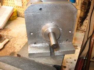
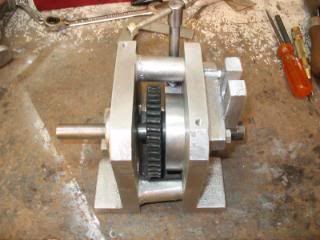
I went ahead and purchased the worm and worm wheel gears from Mc Master Carr. I have the start of the dividing head cast and machined here's a couple of photos.
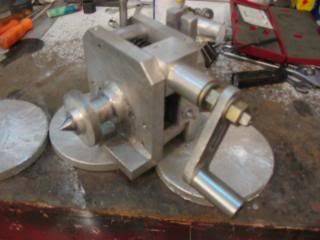
this is the front of the frame
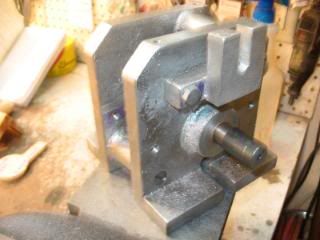
The back side of the frame with the attached foot so it can be mounted horizontal or vertical.
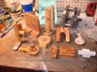
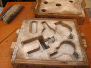
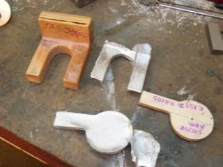
This all of the patterns I have made,only pattern left to make is the indexing plate pattern. These patterns are made from scrap wood and MDF coated with varnish and waxed. The white one I tried some cheap spray paint on it just to see how it would work for a finish I think the varnish works better..
I hope to be able to cast most of the patterns today. I started machining the steel parts and will post photos later.
now Greg Hornbostel you know why this is in the foundry section it being made from castings.
this is the front of the frame
The back side of the frame with the attached foot so it can be mounted horizontal or vertical.
This all of the patterns I have made,only pattern left to make is the indexing plate pattern. These patterns are made from scrap wood and MDF coated with varnish and waxed. The white one I tried some cheap spray paint on it just to see how it would work for a finish I think the varnish works better..
I hope to be able to cast most of the patterns today. I started machining the steel parts and will post photos later.
now Greg Hornbostel you know why this is in the foundry section it being made from castings.
Last edited by norman on Sat Mar 18, 2017 10:54 pm, edited 2 times in total.
Re: building the gingery dividing head
Here's an up date on the progress.
this is the brake to lock the worm wheel
worm wheel in place
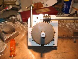
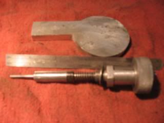
this is the indexing pin shaft that will fit inside of the crank handle
small parts of the indexing pin are made from the casting's spruce
this is the brake to lock the worm wheel
worm wheel in place
this is the indexing pin shaft that will fit inside of the crank handle
small parts of the indexing pin are made from the casting's spruce
Re: building the gingery dividing head
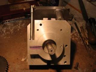
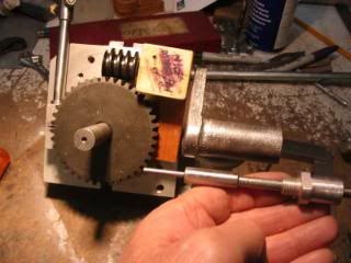
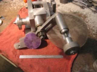
both sides on with the worm wheel in place
fitting the worm gear to the worm wheel
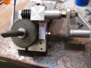
crank handle in place
this will go inside of the crank handle ,the 1/8" pin on the left will index in the plates
the small plate is a unfinished indexing arm,
fitting the worm gear to the worm wheel
crank handle in place
this will go inside of the crank handle ,the 1/8" pin on the left will index in the plates
the small plate is a unfinished indexing arm,
Re: building the gingery dividing head
indexing pin assembly installed in the crank handle,one of the unfinished indexing plates is on the right side. On the left side is the unfinished casting that will be the index plate carrier.
these will soon be machined and drilled, plates
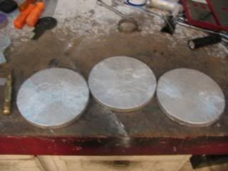
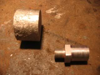
ready to close up the mold. I have 5 parts in there Some times things don't always go good I had 2 of the patterns leak out of the bottom.
These are the 2 parts that leaked out no big deal I'll just remelt them. The leak happened because I didn't plug a vent hole good enough.
I'm now working on the plates so I'm getting close to having this project done.
these will soon be machined and drilled, plates
ready to close up the mold. I have 5 parts in there Some times things don't always go good I had 2 of the patterns leak out of the bottom.
These are the 2 parts that leaked out no big deal I'll just remelt them. The leak happened because I didn't plug a vent hole good enough.
I'm now working on the plates so I'm getting close to having this project done.