Installing a wedge QCTP on the HQ800V
Posted: Thu Aug 12, 2010 12:28 am
Note: most of this will be old hat to anyone with experience. I wrote it for other newbies like me who are confused by the whole topic.
Over the past few months, I read all about the advantages of a quick change tool post and the various types available. I eventually decided I wanted a wedge type, which are reputed to lock in more solidly than the piston type as the wedge pulls the holder in and down. I looked at making my own, but decided my skills weren't there just yet; tool holders I'll attempt, but the QCTP itself is something I resigned to purchase. I read about the pros and cons of Chinese and Indian offerings vs the expensive brands and decided to risk an inexpensive ($130) Chinese one from e-Bay.
Comparing the dimensions of the various sizes to the dimensions of the 800V, I determined the best fit would be the BX / 200 series size. The base is the right area for the compound and the height should readily position any height tool on centre. The only fly in the ointment was the fact that the mount would need to be modified.
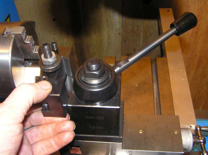
Here's the stock parts, with the base removed:
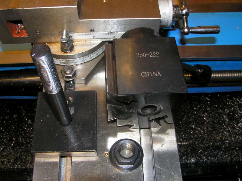
Removing the base is a simple matter of unscrewing the large flanged nut from the top. The rod is threaded 5/8" NF on both ends. The entire wedge assembly then lifts right off as a unit.
Of course, being a curious fellow, I wanted to see how it worked. With the base removed, the wedges can retract all the way off:
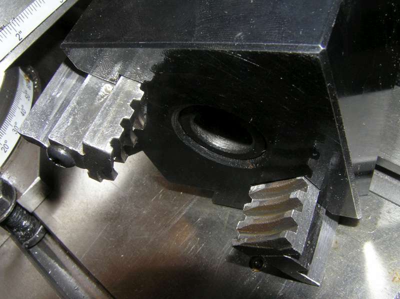
From the side, you can see the worm screw. Turns out this is a multi-start thread and unscrewing it far enough to remove the wedges qualifies as a Bad Idea(tm). Kind of like removing the jaws from a chuck without knowing which one goes in which slot. Now we have to experiment to find the right combination so that a) the wedges rise and fall in unison and b) the lever ends up in a good place -- as in, not directly over the wedges when trying to change tools! So do yourself a favour and leave them where they are. Satisfy your curiosity from the picture:
Ok, back to the installation then. Step one was to unscrew the centre MT rod and drill out the threaded hole to 5/8" -- same diameter as the rod. Also, I drilled and tapped a bolt hole to accommodate a key:
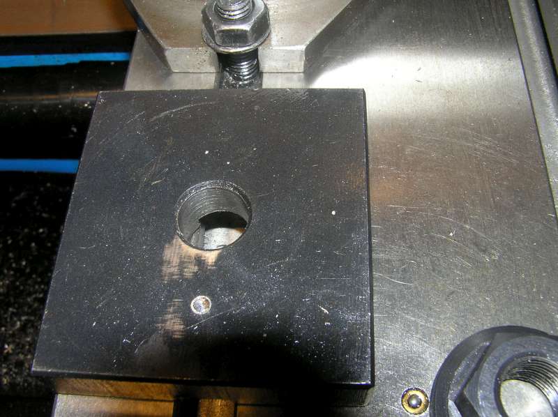
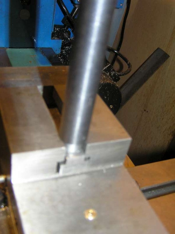
A slot, sized the same as the compound slot, was milled in the underside to accept the key:
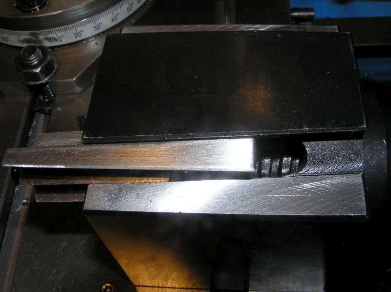
Next, I turned down the end of the MT rod to a couple of thou under the same width. A few more thou off the end allowed me to thread it for 7/16 NF:
This will allow the rod to pass through the compound t-slot:
A custom t-nut was milled from CRS to complete the package:
Another option I considered was to simply cut the threads off the end, and turn a groove in the MT rod. However, that wouldn't have left much up top for the big nut and it wouldn't provide as much contact area as a t-nut:
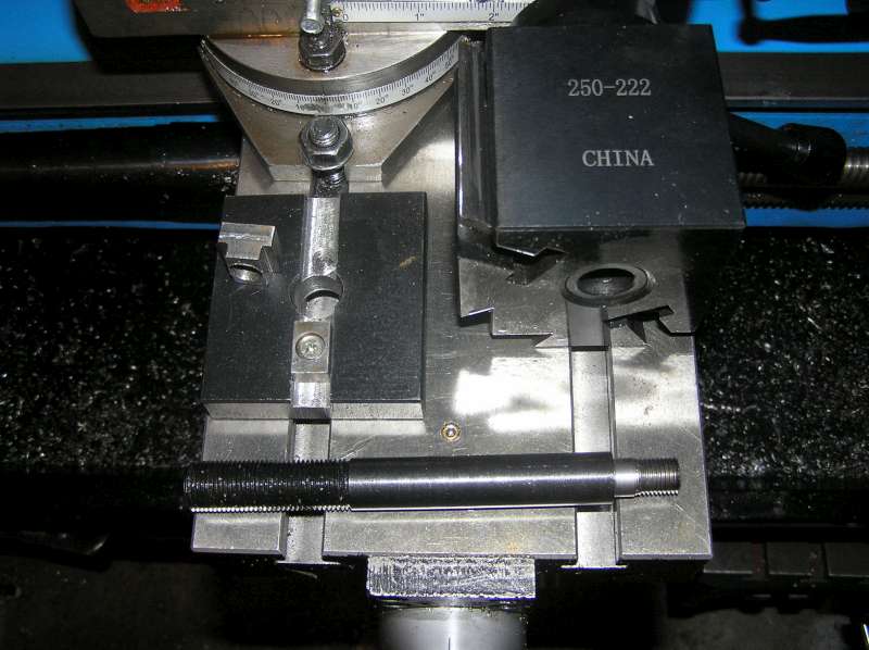
Here's all the parts, as modified:
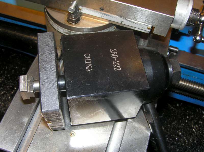
And assembled:
Ok, with the wedges correctly assembled to the worm screw, here's where the handle ends up when locked:
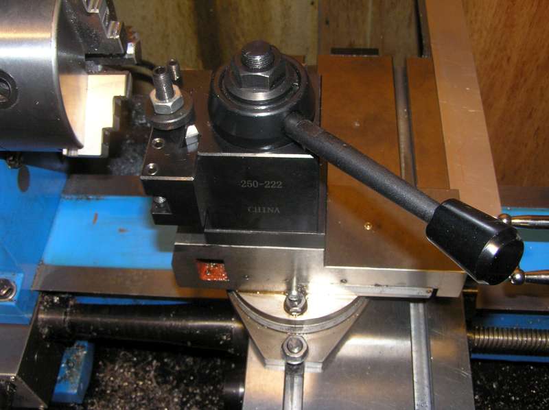
and unlocked:
The post came with a selection of toolholders. From top to bottom they are: 202, which is just like 201 (below) except with a groove in the bottom so it can also accommodate round tools like boring bars. 201 is the basic plain-jane tool holder for square tools up to 1/2". It will take a tool on either end, so you could put a turning tool on one side and a facing tool on the opposite end. 204 accepts 1" shank boring bars, with a sleeve to adapt 3/4" shank bars. 207 is a parting tool holder. Oddly enough, while the other holders accept up to 1/2" tool bits, the parting tool holder accepts up to 11/16" blades and is too big for 1/2" blades without a shim or two. Guess I'll have to buy some bigger blades. Finally, 210 is a weird combination knurling tool and facing tool holder (not sure if I'll ever use the knurler, I have a scissors type already):
Shortcomings:
1. Allen key setscrews on the toolholders. I can see where those are going to fill with chips eventually. I like the square headed setscrews on the original turret post. I think I'll make some to fit these toolholders.
2. it needs something with a lever to replace that nut on top. It's a PITA to keep reaching for a 1" wrench to change the tool angle.
3. I need to figure out some way of indexing the angle of rotation. It would be nice to have a positive stop when square and at least at 29° (for threading).
On the plus side, the wedge action is exactly as advertised: with the locknut loose, the adjuster is easily turned to quickly fine tune the height. But when the lever is locked, the adjuster is snugged right down against the toolpost and cannot be turned by hand. The locknut is really just necessary to prevent inadvertent changes when the holder is kicking around the tool box.
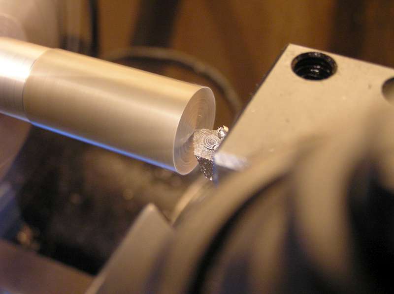
Oh, and did I mention how quick and easy it is to fine tune the height? Actually, I'm kind of glad I spent the first 6 weeks wrestling with shims every time I needed to change tools. I now fully appreciate just how quick and easy it is to fine tune the height. Perfect facing with no shims!
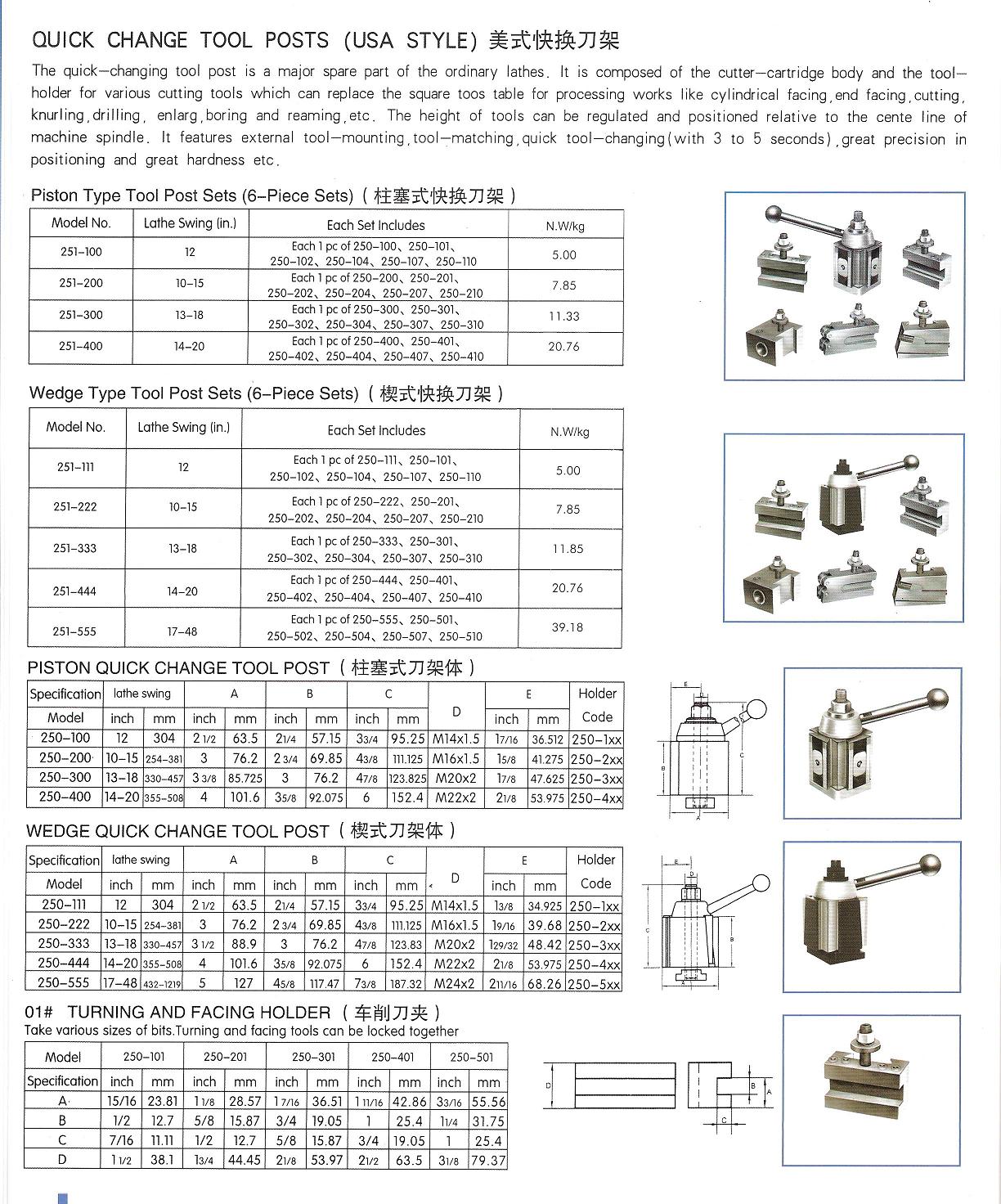
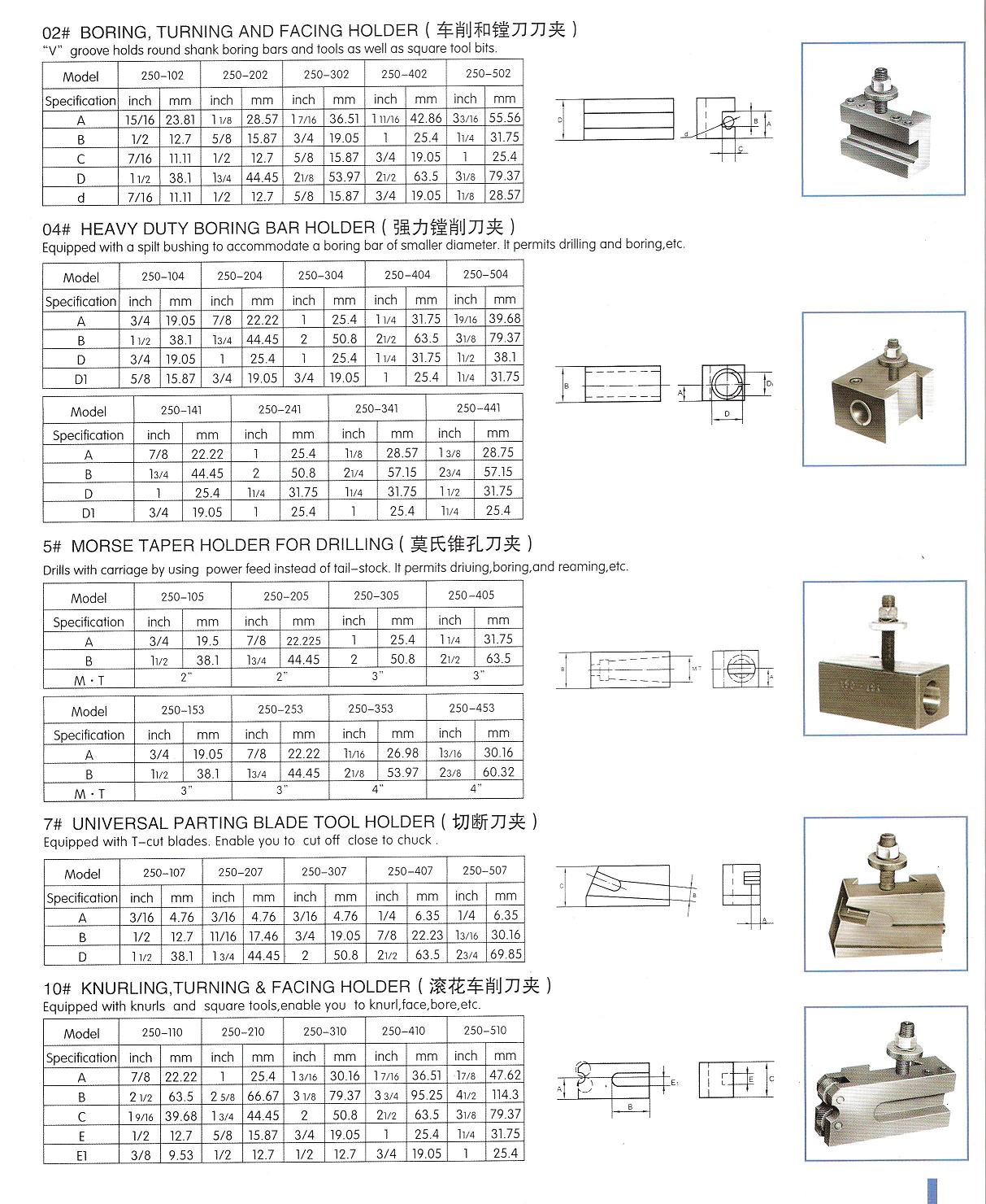
For those trying to figure out what tool fits different machines, here's the dimensions sent to me by the factory:
click here
click here
For those still confused by the whole "BXA / 200 series" designations, here's what they mean:
The "AXA" type designation is Aloris sizing. Yuasa, Phase II, etc. use 100, 200, etc.
AXA = piston type = size 100 (2 1/2" wide, 14mm dia t-nut) = 1/2" tool bit, 3/4" boring bar = model 250-100 .
AX = wedge type version in size 100 = model 250-111
BXA = piston type = size 200 (3" wide, 16mm t-nut) = 5/8" tool bit, 1" boring bar = model 250-200
BX = wedge version of size 200 = 250-222
CXA = piston version of size 300 (3 1/2" wide, 18mm t-nut) = 3/4" tool bit, 1" boring bar = model 250-300
CX = wedge version = model 250-333
CA = size 400 (4" wide, 22mm t-nut) = 1" tool bit, 1 1/4" boring bar = 250-401
DA = size 500 = 250-501
Over the past few months, I read all about the advantages of a quick change tool post and the various types available. I eventually decided I wanted a wedge type, which are reputed to lock in more solidly than the piston type as the wedge pulls the holder in and down. I looked at making my own, but decided my skills weren't there just yet; tool holders I'll attempt, but the QCTP itself is something I resigned to purchase. I read about the pros and cons of Chinese and Indian offerings vs the expensive brands and decided to risk an inexpensive ($130) Chinese one from e-Bay.
Comparing the dimensions of the various sizes to the dimensions of the 800V, I determined the best fit would be the BX / 200 series size. The base is the right area for the compound and the height should readily position any height tool on centre. The only fly in the ointment was the fact that the mount would need to be modified.
Here's the stock parts, with the base removed:
Removing the base is a simple matter of unscrewing the large flanged nut from the top. The rod is threaded 5/8" NF on both ends. The entire wedge assembly then lifts right off as a unit.
Of course, being a curious fellow, I wanted to see how it worked. With the base removed, the wedges can retract all the way off:
From the side, you can see the worm screw. Turns out this is a multi-start thread and unscrewing it far enough to remove the wedges qualifies as a Bad Idea(tm). Kind of like removing the jaws from a chuck without knowing which one goes in which slot. Now we have to experiment to find the right combination so that a) the wedges rise and fall in unison and b) the lever ends up in a good place -- as in, not directly over the wedges when trying to change tools! So do yourself a favour and leave them where they are. Satisfy your curiosity from the picture:
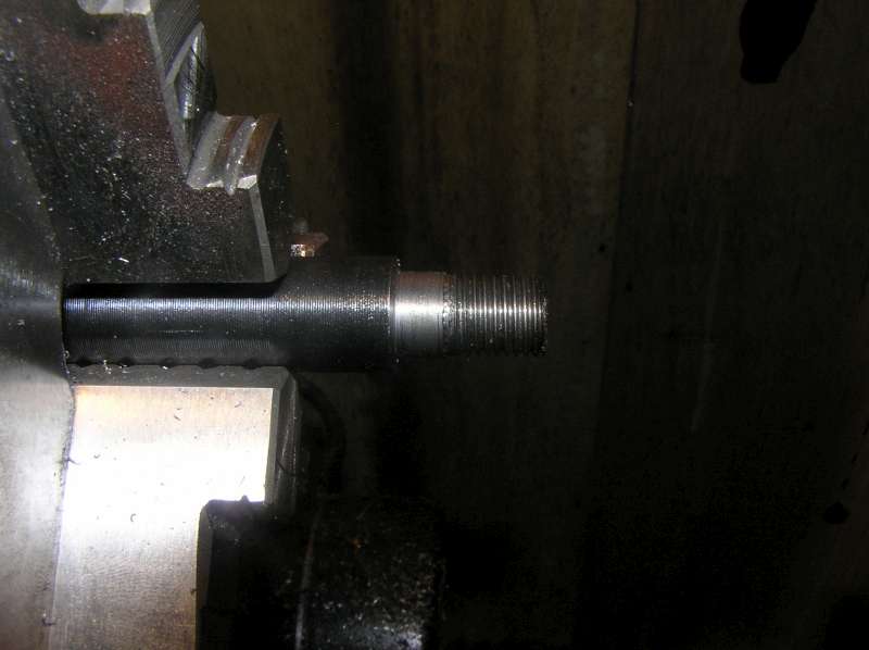
Ok, back to the installation then. Step one was to unscrew the centre MT rod and drill out the threaded hole to 5/8" -- same diameter as the rod. Also, I drilled and tapped a bolt hole to accommodate a key:
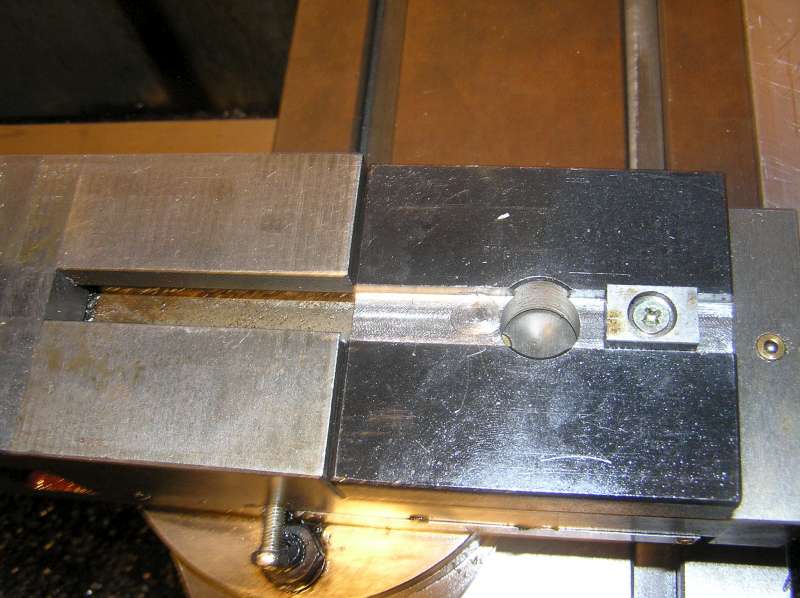
A slot, sized the same as the compound slot, was milled in the underside to accept the key:
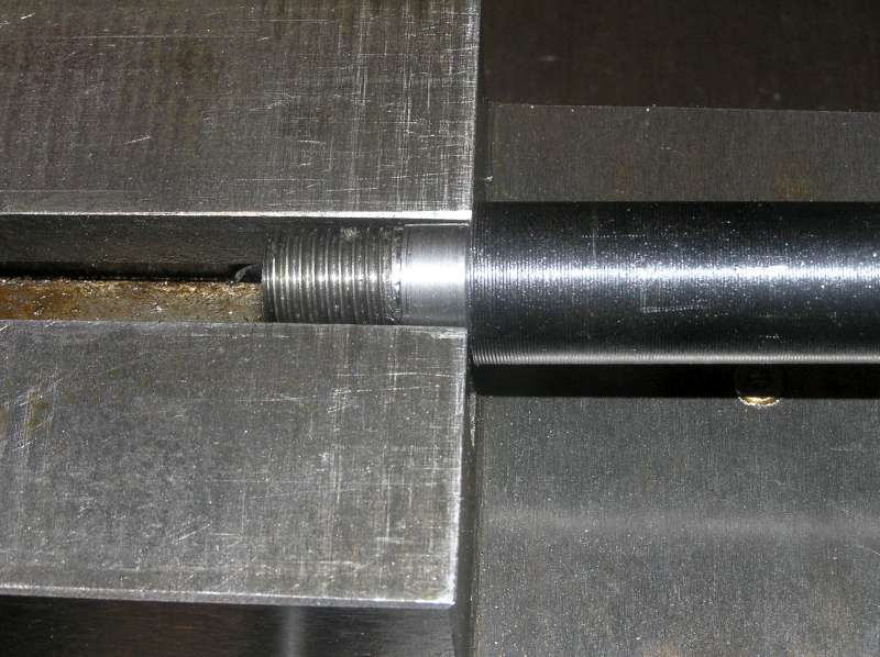
Next, I turned down the end of the MT rod to a couple of thou under the same width. A few more thou off the end allowed me to thread it for 7/16 NF:
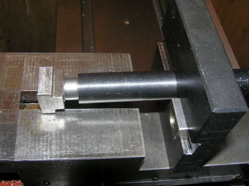
This will allow the rod to pass through the compound t-slot:
A custom t-nut was milled from CRS to complete the package:
Another option I considered was to simply cut the threads off the end, and turn a groove in the MT rod. However, that wouldn't have left much up top for the big nut and it wouldn't provide as much contact area as a t-nut:
Here's all the parts, as modified:
And assembled:
Ok, with the wedges correctly assembled to the worm screw, here's where the handle ends up when locked:
and unlocked:
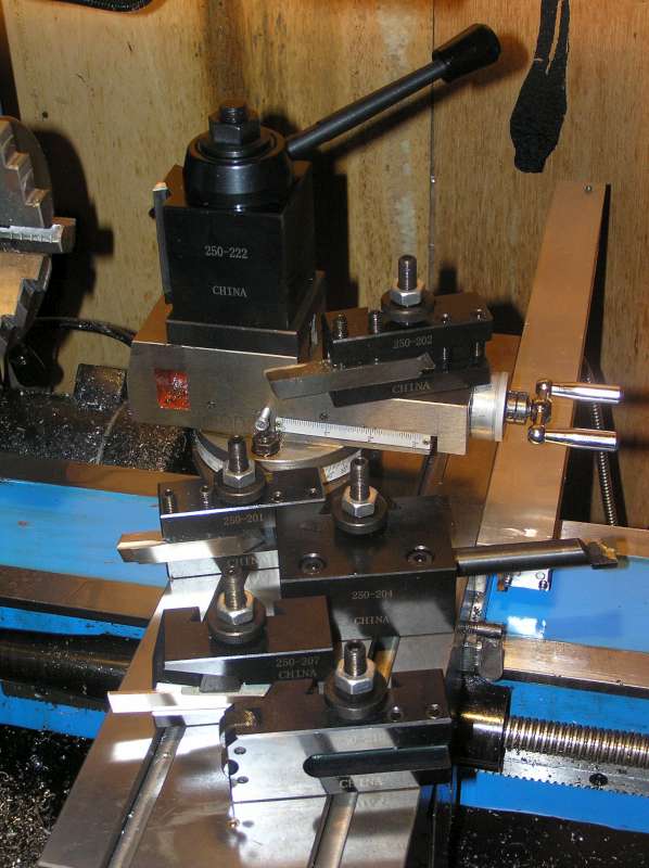
The post came with a selection of toolholders. From top to bottom they are: 202, which is just like 201 (below) except with a groove in the bottom so it can also accommodate round tools like boring bars. 201 is the basic plain-jane tool holder for square tools up to 1/2". It will take a tool on either end, so you could put a turning tool on one side and a facing tool on the opposite end. 204 accepts 1" shank boring bars, with a sleeve to adapt 3/4" shank bars. 207 is a parting tool holder. Oddly enough, while the other holders accept up to 1/2" tool bits, the parting tool holder accepts up to 11/16" blades and is too big for 1/2" blades without a shim or two. Guess I'll have to buy some bigger blades. Finally, 210 is a weird combination knurling tool and facing tool holder (not sure if I'll ever use the knurler, I have a scissors type already):
Shortcomings:
1. Allen key setscrews on the toolholders. I can see where those are going to fill with chips eventually. I like the square headed setscrews on the original turret post. I think I'll make some to fit these toolholders.
2. it needs something with a lever to replace that nut on top. It's a PITA to keep reaching for a 1" wrench to change the tool angle.
3. I need to figure out some way of indexing the angle of rotation. It would be nice to have a positive stop when square and at least at 29° (for threading).
On the plus side, the wedge action is exactly as advertised: with the locknut loose, the adjuster is easily turned to quickly fine tune the height. But when the lever is locked, the adjuster is snugged right down against the toolpost and cannot be turned by hand. The locknut is really just necessary to prevent inadvertent changes when the holder is kicking around the tool box.
Oh, and did I mention how quick and easy it is to fine tune the height? Actually, I'm kind of glad I spent the first 6 weeks wrestling with shims every time I needed to change tools. I now fully appreciate just how quick and easy it is to fine tune the height. Perfect facing with no shims!
For those trying to figure out what tool fits different machines, here's the dimensions sent to me by the factory:
click here
click here
For those still confused by the whole "BXA / 200 series" designations, here's what they mean:
The "AXA" type designation is Aloris sizing. Yuasa, Phase II, etc. use 100, 200, etc.
AXA = piston type = size 100 (2 1/2" wide, 14mm dia t-nut) = 1/2" tool bit, 3/4" boring bar = model 250-100 .
AX = wedge type version in size 100 = model 250-111
BXA = piston type = size 200 (3" wide, 16mm t-nut) = 5/8" tool bit, 1" boring bar = model 250-200
BX = wedge version of size 200 = 250-222
CXA = piston version of size 300 (3 1/2" wide, 18mm t-nut) = 3/4" tool bit, 1" boring bar = model 250-300
CX = wedge version = model 250-333
CA = size 400 (4" wide, 22mm t-nut) = 1" tool bit, 1 1/4" boring bar = 250-401
DA = size 500 = 250-501