Help me Rebuild a Smithy CB-1220

This forum is dedicated to those hobbyists with the 3-in-1 metalworking machines. Mill-Drill-Lathes. Tips, techniques, modification and use of these machines is topical.

Moderator: Harold_V

Post Reply
User avatar
rodw
Posts: 20
Joined: Fri Nov 30, 2012 6:29 am

Help me Rebuild a Smithy CB-1220

Post by rodw »

Hi guys, thought I'd join up as this is one of the few boards that has a 3-in-1 section and I've lurked for a while. I've had my Machine for about 3 years (bought second hand) and have finally got to a stage I am reasonably confident with it now.

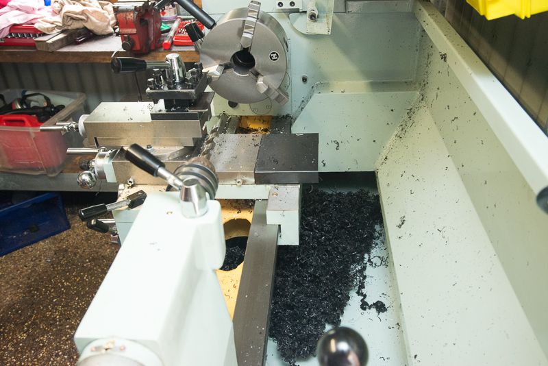
Anyway, disaster struck a week ago as I had a lot of oil pooled around it which I initially thought was coming from a hole in my oilcan but I found it was dripping from the lathe spindle behind the cover. so I started to disassemble it and found the large sealed outer bearing that the pulley attaches to had sprung a leak, grease had run out of it and the oil must have been going though the bearing seals. Somewhere along the line, I tapped the spindle when I should not have and it came out of the rear bearing. So now I am forced into doing something which I was hoping to be avoided; a full strip down to replace the front oil seal.

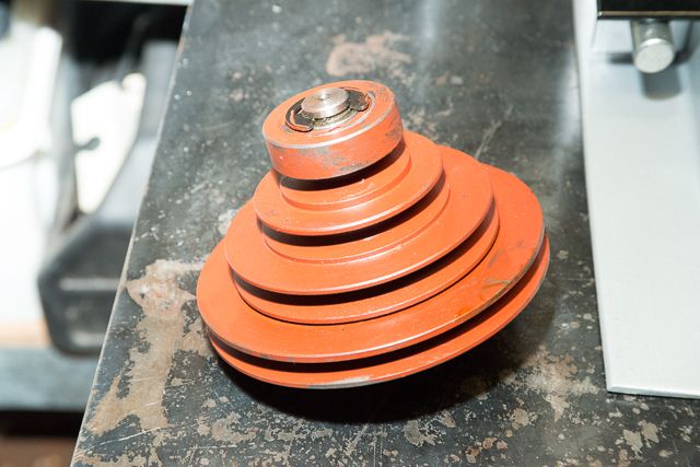
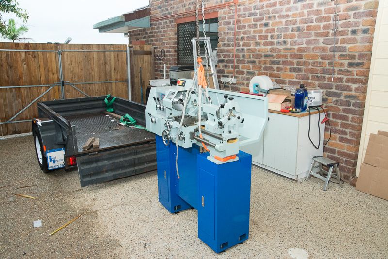
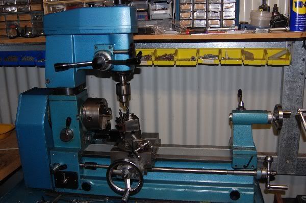
I've got a bunch of part on order from Smith and while I am waiting, I taken my time to strip it down. So I was hoping that there wold be a few guys on this board that might be able to help me restore this:
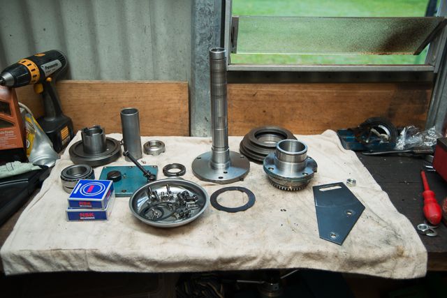
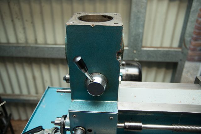
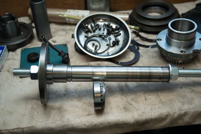
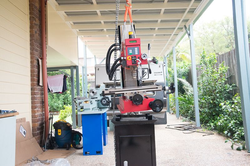
Image

Image

Image

Image

to this

Image

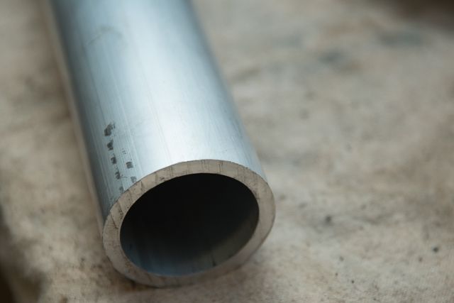
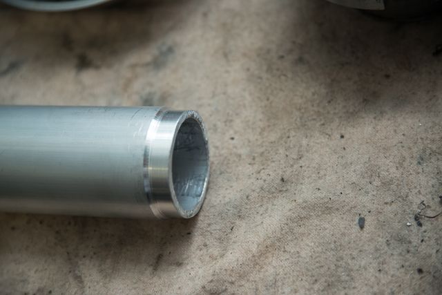
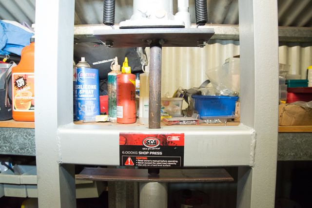
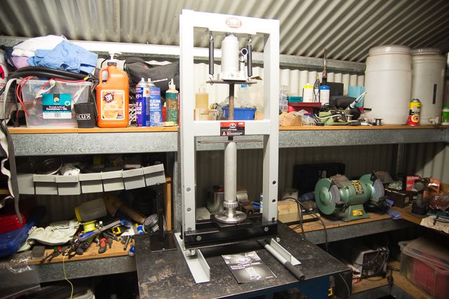
I am a bit concerned about how to press the spindle bearings back into the headstock and set the preload. I think I need a piece of threaded rod and a tube that fits over the inner shaft and wind the together but all ideas would be appreciated.

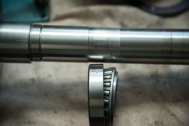
I am sorry I did not take a few more photos while I disassembled it. The hardest part was pulling off the front spindle bearing. It is not possible to do this without wrecking the front oil seal so an 11:00pm phone call to Smithy in the US got some parts underway.

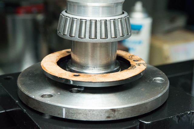
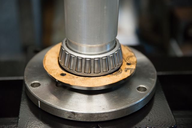
I took the shaft to work one day with the intention of asking for some ideas to get this apart but then I remembered that there was a bearing splitter in my hydraulic gear puller set so that night, I gave it a go. For some reason, it was missing a couple of bolts so I used the extensions in place just to hold it together.

Image

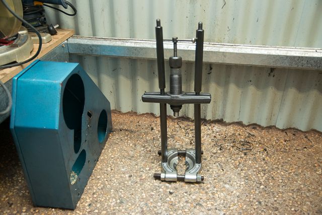
The puller did the trick, but it was quite slow and I had to reset the position half a dozen times due to limited travel.

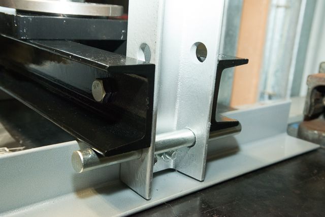
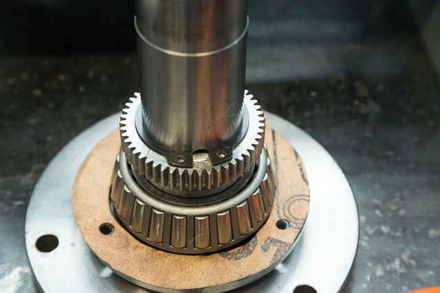
The other bit which I thought hard about was removing the flanged pulley seat at the back of the machine. This had to come off because the rear bearing was in pieces behind it. I started by giving it a tap to separate any gasket but this did nothing. Then I realised it had to be flanged on to accurately centre the pulley. I figured it could not be pressed in as there were 4 bolts holding it on There was a groove around the outer flange and I wondered why they had bother to machine this in. Finally I decided this was to allow them to use a bearing splitter bigger than the one I had to pull this off. I decided before I went looking for a bigger splitter to try prising it off gently with a wood chisel. This worked a treat and slowly tapping it round until I could get the fat of a screwdriver behind it made it an easy job. Soon it was off and I found the bevel gear that drives the mill was mounted on the rear side.

Image

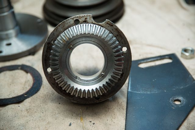
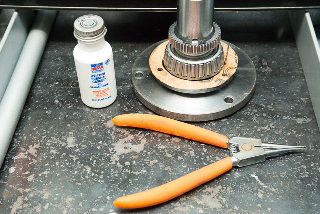
Once got this off, I realised I had not ordered the gasket from Smithy, so I'll have to make one up.

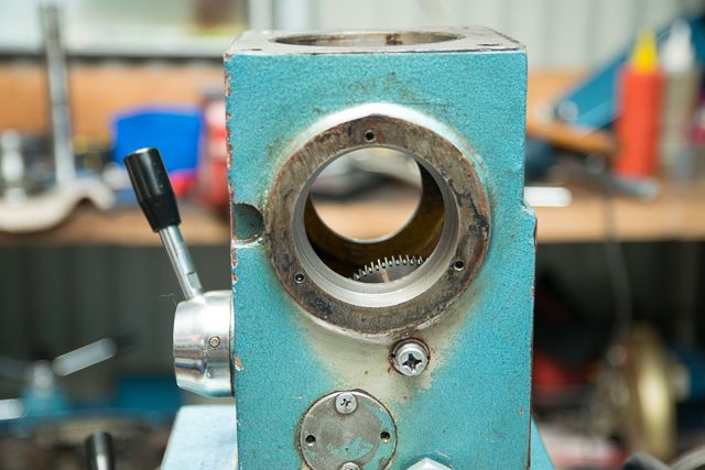
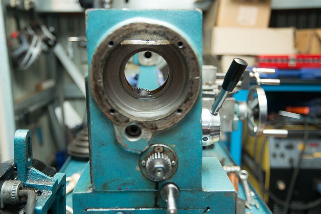
I was able to knock out the outer spindle bearing seats with a brass rod. The rear one was seated against a shoulder, the front one was not fully seated so that makes me wonder about this whole preload thing.

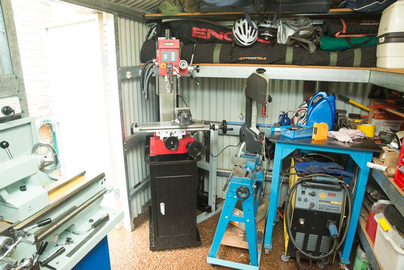
So anyway back onto the build. Here are a few questions:

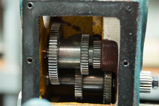
1. Should I bother stripping the gearbox down any further? This all seems to be in good order.

Image

2. How to fit the spindle bearing outer cones? I think the front one must get seated as part of setting the preload

3. How to press the rear spindle bearing onto the shaft?

Cheers guys, I hope you can help. I will try and document how it all goes back together with pics.
RodW
Brisbane, Australia
http://www.vehiclemods.net.au
Torch
Posts: 1684
Joined: Wed Mar 17, 2010 7:58 am
Location: Muskoka

Re: Help me Rebuild a Smithy CB-1220

Post by Torch »

If you go to the Grizzly website and download the G4791 manual, it has two pages of preloading the lathe bearing. If you can't get the proper specs and procedure for your specific machine you might want to review this as it appears to be similar in design.
User avatar
rodw
Posts: 20
Joined: Fri Nov 30, 2012 6:29 am

Re: Help me Rebuild a Smithy CB-1220

Post by rodw »

Torch wrote:If you go to the Grizzly website and download the G4791 manual, it has two pages of preloading the lathe bearing. If you can't get the proper specs and procedure for your specific machine you might want to review this as it appears to be similar in design.
Torch, Thanks for that. It is very helpful info and I will follow this method. There are some differences to mine, which has a bevel gear to drive the mill head in the road so there is a sleeve between the nut on the back of the shaft and the bearing.

Before I get to preload I have to press the bearing races on. The front one is pretty easy as it can be pressed on to the shaft in a press so I'll get somebody to do that. About a week ago I resisted the urge to buy a 12 ton press that was on special at $150 because I had nowhere to put it! :(

The back bearing has to be pressed onto the shaft when the shaft is fitted up in the headstock. Yesterday I bought a piece of 3/4" threaded rod and a couple of nuts. I have seen somewhere where a piece of rod like this can be used to pull the bearing on to the position shown in this pic. What a drama this simple purchase was in a country where everything is metric! The only threaded rod was imperial and (almost) the only nuts were metric! Took me about 20 minutes before I finally found the 3/4" nuts and washers which were about 8 shelves away from the smaller imperial nuts and bolts ....

Image

There is a sleeve that goes over the shaft between the threaded end and the rear bearing (which you can see standing up behind the chuck flange) but the thread is tight and I don't think the thread will be able to be engaged until the bearing is pretty well seated so I am going to get a piece of aluminium tube that fits over the flange to let this threaded rod do its job. I will also use this to press on the front bearing. The reason I will use ally is simply because I can buy it cut to length near where I live :)

Image

Its hard to see but there is a very slight thickening of the shaft where the rear bearing is seated. Actually, looking at this photo now, I can see that the bearing was never seated to the shoulder and the amount it was short just happens to look like the difference between the front bearing collar and the seat it should have been in. This may help to explain why the thing fell apart on me so easily when I did the wrong thing.

Today's job is to clean it all up and make a gasket for the rear flange out of the correct thickness gasket material I was lucky to be able to buy. I ended up with a 1.5m (5') roll of the stuff for $20. If I had of remembered to order the gasket from Smithy, it probably would have only cost 50 cents :(

Anyway, thanks again, if there are any other ideas, please post them up. I am slowly gaining a bit more confidence about getting this back together.
RodW
Brisbane, Australia
http://www.vehiclemods.net.au
User avatar
rodw
Posts: 20
Joined: Fri Nov 30, 2012 6:29 am

Re: Help me Rebuild a Smithy CB-1220

Post by rodw »

Well, I have made a bit more progress. Yesterday I cleaned up everything and made a couple of gaskets. I also found a scrap of waterpipe which is the perfect size to press on the rear spindle bearing with the threaded rod. That still left the fitting of the front bearing unresolved. I went to Action Aluminium today on the way home and picked up an offcut of aluminium tube that has 50mm outside diameter and a 5 mm wall thickness. The inner diameter of 40mm is an easy push fit over the bearing shaft.

Image

The outer diameter was a bit too big and would have made contact with the bearing cage. I was lucky because Chris who lives in my street was home so I stopped and I asked him if he could turn it down for me which he did while I waited. His current project is a steam engine that will be about 1 horsepower when complete to drive a generator to charge his caravan batteries when bush camping :o

Image

I also picked up a bottle of gasket sealant on the way home too so I think now all I have to do is wait until the parts arrive from the US which I hope will be later in the week.

I noted Chris has a press down the road, so I might drop down with a six pack when I am ready for the bottom bearing to be pressed on... It'll give me an excuse to see how his steam engine has progressed :D
RodW
Brisbane, Australia
http://www.vehiclemods.net.au
User avatar
rodw
Posts: 20
Joined: Fri Nov 30, 2012 6:29 am

Re: Help me Rebuild a Smithy CB-1220

Post by rodw »

Sorry, this thread has been bit quiet while I have been waiting for my parts to arrive from Smithy in the US. The good news is that they arrived today but I got a bit distracted on another related project.

While I was waiting for my parts to arrive, I was dreaming. I thought about maybe building a shop press and building it into my shop when I rework the shelves to make more storage. There is a company down under called Super Cheap Autos and they do a few cheap tools. I don't like them much because they charge through the nose for poor quality tools. I happened to look at their web site last night and they had their small 6 tonne press on special at half price marked down from $199 to $99. This is pretty good value given that I could not buy a hydraulic hack for less than about $65. $199 is way over the top when I can buy a 20 tonne full height press for $268 a block away at Trade Tools Direct.

Anyway, I decided I'd grab this little press as it was small enough to squeeze into my shop as it is designed to be a bench top model. I got it home and found that the throat of it was not big enough to get the spindle under it. This was not totally unexpected so I set about modifying it. First job was to drill some extra holes in the frame to drop the brace down a bit lower.

Image

The pins sit about 2mm above the angle iron feet. A quick squirt of silver paint and it looks like a bought one again!

This was a pretty easy job. Because it was so small, I was able to place the frame in my drill press vice while supporting the frame on my welding table. This let me drill a 16 mm hole straight though both sides of the channel iron in one pass.

I still did not have enough clearance for the spindle. The easiest way to fix this would have been to cut the end off the press rod but I did not want to do this to a brand new as yet unused tool so I decided to make a new press rod from some 100mm x 8mm flat bar and some 3./4" rod I had here. The rod I used is a bit smaller than the original one but it seems that it will work fine. This is what I came up with:

Image

I think I better paint this part once I have the lathe together :(

Beautiful! All ready to start rebuilding my Smithy :)

Image

The quick modifications I did have opened up the throat of this small press from a quoted 230mm (9") to a much more useful 350mm (15"). I may end up extending the frame by welding some extended legs on when I get around to permanently installing my little press. My next workshop mod is to cut away the bench where the jumble of tools are below the droopy plastic drawers. This will let me put in a wheeled tool chest in there to tame the jumble of tools on the bench below the grey drawers. This will mean the shelves will need some new legs to support them. I am thinking I might use the Press as the legs and on the odd occasion it is needed, I could simply wheel out the drawer unit to gain access to the press.

Anyway, back to this build up. The other thing I decided to order from Smithy was their planetary gear set which provides a 50% reduction in spindle speed.

Image

It will be interesting to see what difference this will make. From memory, the minimum speed is around 160 rpm so fitting this will drop that to about 80 rpm which might let me try my hand at threading. The drive belt from the motor goes to the large pulley at the back and the three front pulleys in the sheave are identical in layout to the factory pulley. It seems that the drive direction will be reversed which might take a bit of getting used to but my power switch is not labelled. Later in the build up, I will try and remember to take some photos of this gear set when I strip it down.

So the next job now is to fit the felt washer to the front oil seal and press the front bearing on. From there, it should be pretty plain sailing, replacing the spindle cog and pressing on the back bearing with the thread rod I showed earlier.

Oh and before I forget and slightly OT, my bubble blowing Santa wanted to pass on his regards for the festive season!

Image

Give him a wave if you happen to drive past!
RodW
Brisbane, Australia
http://www.vehiclemods.net.au
User avatar
rodw
Posts: 20
Joined: Fri Nov 30, 2012 6:29 am

Re: Help me Rebuild a Smithy CB-1220

Post by rodw »

Well, parts have arrived and I have fitted them which was pretty easy really.

The first step was to soak the new felt seal overnight in lathe oil and fit it to the plastic oil seal housing. The housig was not very flat so I gave it a light rub with sandpaper to level the mating surface. I decided it would be best to make sure the join in the seal was at the top. Check the way the bolt holes are oriented and mark one that is at the top. start pushing the seal in from the middle of the felt strip at the point opposite the mark. To fit the oil seal, I used a jewellers screwdriver to gently ease the felt on to the shaft.

Not shown in the Smithy Parts manual was a gasket between the oil seal and the headstock but one was fitted to my lathe. I made one up from gasket material.

All ready to press on.

Image

Pressing the bearing on was very easy with my little press. tonnes was more than enough even though I could hear the part making noises as it went on.

Image

You can see the marks I made to show the top position and to align the seal with the hole in the chuck flange to get screw driver to it.

Then fit the gear to the shaft. I used the press again to make it easy but it really is a push fit. Replaced the circlip.

Image

Finally a pic of the completed job and the gasket goo I used to seal the gasket. Buying the correct circlip pliers made it a cinch to fit the circlip.

Image

That's all I have time for now, more to come!
RodW
Brisbane, Australia
http://www.vehiclemods.net.au
shepdog
Posts: 51
Joined: Tue Jun 20, 2006 2:21 pm

Re: Help me Rebuild a Smithy CB-1220

Post by shepdog »

any progress on this/ im stuck right at this pint om my b2229 rebuild....does that gear fit through the bearing race? mine doesn't.... :?
toddalin
Posts: 284
Joined: Tue Nov 13, 2012 1:10 pm
Location: Orange County, CA
Contact:

Re: Help me Rebuild a Smithy CB-1220

Post by toddalin »

At least you are dealing with Smithy. They've been a pleasure to deal with and I have very positive things to say about their service! :D
User avatar
rodw
Posts: 20
Joined: Fri Nov 30, 2012 6:29 am

Re: Help me Rebuild a Smithy CB-1220

Post by rodw »

I am sorry guys. It does not look like I took any more photos of this and I recently sold this machine on ebay and moved to separate AL320G 13" lathe and Sieg Super X3 mill.

I will say it all went together fine, you have to reassemble the bearing on the other end after fitting the spindle to the headstock and I was able to "pull" the bearings together with a piece of 3/4" threaded rod through the spindle I bought for the purpose.

My Smithy was still running very nicely when I sold it after this repair, just the new machines were on special and a bit of an upgrade from what I had!

I hope you don't mind me deserting the 3-in-1 club. I do think it was a good, affordable introduction to machining and don't regret buying it at all!

Image

Image

Image

Image
RodW
Brisbane, Australia
http://www.vehiclemods.net.au
Post Reply