Topics include, Machine Tools & Tooling, Precision Measuring, Materials and their Properties, Electrical discussions related to machine tools, setups, fixtures and jigs and other general discussion related to amateur machining.
Needing a bigger mill for rigidity and function became apparent a few years back so I set out to find one that would fit in my shop. Space is extremely limited and a full size Bridgeport style mill simply would not work. I thought I found one that would suite but as it turns out the spindle to table space is shy of about 4" clearance when I have my tilting rotary table which is a principal piece of equipment for what I do so I decided a riser block was necessary.
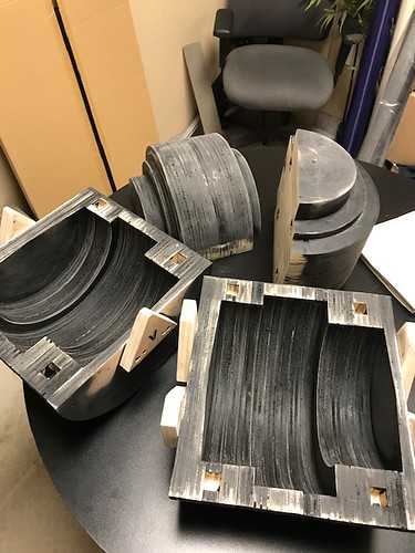
After searching the globe (literally LOL) I come to find they did not make one for my machine size (3/4" bridgport clone) so I set out to make one. I posted here a while back about machining one from various materials/methods but is was apparent the best thing for rigidity and vibration damping was cast metal so I set out to learn about cast one. I spoke to a local foundry and they were very helpful, which was a pleasant surprise considering my experience with most large industrial companies brushing us small guys off thinking we take up their precious time and want something for free. He explained that I need a pattern with a core mold. I learned how to make one with al the tapers and built one from plywood.
Because my shop is so tight I had to figure out a way to get the head and ram off without being able to get a hoist in over the top so I came up with this column idea which has proven to work quite well.
Now that I'm this far I ran into a small issue with the bolts....how do I get them out?
My thought is to leave them in and make extensions for them or drill/tap the block to accommodate them, then lock the riser down with new bolts and the existing spider. The only other option I see is to try to slide the ram out of the cradle far enough to get the bolts out.
I'd appreciate some advise on this matter if I could as I'm not sure what the best method is at this point.
Thanks in advance.
Vision is not seeing things as they are, but as they will be.
Well! You have gone beyond by actually doing what most wouldn't even consider. Bolts is bolts and cut the tops off. It cannot hinder you further. You will be needing stronger and longer shoulder studs with equally good quality nuts. Everything you do is an improvement or upgraded to meet the modification.
That's a good option but the bolt heads are shrouded by a recess which will make it very difficult to cut off. So I thought of this idea too.....have a look and let me know your thoughts.
Vision is not seeing things as they are, but as they will be.
Thanks for the thoughts guys. I'll work away on it.
I went to a friends shop yesterday to use his lathe to turn the part. He has a 14" x 40" with a tool post capable of holding 1" tool holders. I must say, there would be no hope trying to turn this this on my 12" lathe at all! It was on the limits of the 14" lathe since we couldn't slide the carriage past the front of the part. We got the job done and it turned out better than I expected.
As you can see I was out a bit on meeting the mark in the middle but I can hide that with paint LOL
Vision is not seeing things as they are, but as they will be.
Unfortunately no, the only way to get the head and ram off are to slide the whole unit toward the front but I run out of room ever so slightly. I'm thinking the best method is as I've drawn it by leaving the bolts as they are and lift the whole thing up high enough to get the new riser under it. That way I don't have to worry about taking the ram out at all. I'll just drill and tap the new riser to accommodate short bolts from the bottom.
Vision is not seeing things as they are, but as they will be.
The 3 riser blocks I bought, were mounted exactly as you show. You used the original spider to hold the riser block to the mill and the new spider to hold the ram assembly to the riser block.
Since I've had my mill blown apart to it's major components a couple of times it's not really that time consuming to do it and would make the whole job so much easier. Pull the motor first, use the mills knee with a piece of ply on it to take the heads weight on the end of the spindle nose as the bolts are removed, Gently set the head on some stacked blocking on a near by bench top on the machined face that bolts to the face of the knuckle, pull the knuckle, then remove the retaining bolt for the rams pinion gear and slide the pinion out. Remove the rams gib screws and slide the gib out. The ram will then just slide right out and one person should be able to handle the weight. Then remove the top column cap, reach inside the column through the removed sheet metal on the side of the column and support the spider as those top caps bolts are removed. With the ram out those problem bolts just lift out.It really is a simple job and should take less than an hr. If I was adding that riser it's the only way I'd do the job RSG. I'd also be willing to bet screwing around trying to do it without removing those parts would take longer to cut the heads off and get the riser and new bolts in. Plus it will be a whole lot easier to see what your doing and get all the bolts started.
Very nice job on that pattern and the finished riser. A professional quality result for sure.
Pete, thanks for the comments I appreciate your input as always. I'm really leaning toward doing it how I rendered it for one reason. When the day comes to move it out I must put it back to it's original state in order to get it out of my shop. If I do it this way all I have to do is pull the block, lower in down and re-attach the spider. If however I do it the way you suggest (which I don't doubt is the proper way it should be done) it will make a pile of work for me next year when we finally decide to move. Perhaps then when I have more room to maneuver in the shop I'll do it that way.
Further to your suggestion about pulling the head first to sliding the ram out, I did some thinking today and if I played my cards right I could simply pull the gib on the ram and crank the table out which would slide the whole thing out while it was still sitting on the pedestal I fab'd up. I'm going to try my first method but if it fails I'll do as you said only use the pedestal.
I'll post my progress later.
Vision is not seeing things as they are, but as they will be.