Page 1 of 1
Making micrometer collars
Posted: Fri Feb 11, 2005 9:47 pm
by CharlesM
I need to make some micrometer collars(dials). what is the best way to cut the graduation lines?
Re: Making micrometer collars
Posted: Fri Feb 11, 2005 11:49 pm
by pockets
You might try a headstock indexing device and a tool ground to the cross section of the desired gravings. use the cross slide like a shaper and take VERY light cuts. I have cut small keyways, in brass, with this method.
Re: Making micrometer collars
Posted: Sat Feb 12, 2005 12:41 am
by Keith
Here is a picture of a home made micrometer stop that I marked like "pockets" suggested. I took a strip of paper that was exactly long enough to go around the chuck and marked it with 25 evenly spaced marks. I then attached it around the chuck and clamped a pointer on the lathe temporally. Align the pointer with each mark and scribe. It worked very well.

Re: Making micrometer collars
Posted: Sat Feb 12, 2005 12:46 am
by Harold_V
A pantograph needle works best, but you really need high spindle speed for good results. Anything over 10,000 RPM would likely serve you well, but you can get by with slower speeds so long as you give the needle plenty of time to cut, using slow feed rates. Be sure to keep the needle lubricated. An acid brush will serve well.
Pantograph needles can be had with straight shanks, in both carbide and HSS. Unless you can run fast, I'd suggest using the HSS model, which will be a little more forgiving of errors. The tiny tips are very easy to break.
You'll need some kind of indexing device.
Harold
Re: Making micrometer collars
Posted: Sat Feb 12, 2005 11:40 am
by jutz
Testing an image attachment
Re: Making micrometer collars
Posted: Sat Feb 12, 2005 11:51 am
by jutz
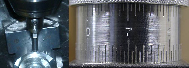
On the left is the setup I used to graduate the dial on the right. I used a diamond drag engraving stylus (McMaster-Carr part 1604T13) in an adapter I made to fit in an end mill adapter. I used a small clamp to prevent accidental rotation of the mill spindle because the adapter holding the stylus is actually for a dial indicator with a larger shank, so the stylus is off center. I used a rotary table (mounted vertically) to position the dial but an indexing attachment on a lathe spindle could accomplish the same thing.
The dial in the picture is Al 7075 but I've used this same stylus on steel and titanium with similar results.
Re: Making micrometer collars
Posted: Sat Feb 12, 2005 12:08 pm
by Hal K
Jutz, How did you manage to get the numbers on your dial markings (using small dots) so uniform and accurately placed? Hal K
Re: Making micrometer collars
Posted: Sat Feb 12, 2005 12:24 pm
by jpfalt
I have cut dials in the past by making a steel stamp holder that I can grab in a collet on a bridgeport mill. I then stamped using the knee raise to get uniform depths. The work was in a spin index fixture.
Re: Making micrometer collars
Posted: Sat Feb 12, 2005 4:17 pm
by jutz
I used the same stylus for the numbers. After some testing, I decided to put the dots 0.014" apart and calculated the rotational angle required to place them that far apart based on the diameter (1") of the dial. Since my rotary table is only graduated to the nearest 20", I rounded the angle to such an increment. The font is straight from a very old, low resolution dot matrix printer. Then it was just a tedious process of impressing dots at the calculated places.
The uniformity of the dots was actually quite simple. I set a dial indicator (Interapid lever type to be specific, although I don't think the type matters much) to read quill travel. While testing, I found that the indicator would show smooth travel of the quill until the stylus touched the work; then there would be a pause while the quill feed took up the backlash. I fed the quill down a consistent distance (0.0025 I think, but I'm not positive) from the "pause point" to get uniformly sized dots. It's actually a lot easier than it sounds. The first few digits took a while but it went fairly quickly once I got a rythm going.
I just wish I hadn't put the numbers on upside down.
Re: Making micrometer collars
Posted: Sat Feb 12, 2005 4:21 pm
by CharlesM
Thanks for all of the responces.
I am making a clearance setting fixture for a tool & cutter grinder.
I will use my rotary table mounted vertically. I will order one of the diamond drag engraving cutters from McMaster-Carr. I will probably make it out of 7075 T6. I have a few pieces in the scrap bin.
Charles McGough
Re: Making micrometer collars
Posted: Sun Feb 13, 2005 1:45 pm
by icemaker
Joel,
I am always amazed at the high quality and professional appearance of your projects. Every time you post something I always file away a future tip or idea that I can use. Nice work. Bill
Re: Making micrometer collars
Posted: Sun Feb 13, 2005 3:32 pm
by cartertools
If you have a CNC mill it is pretty easy (not everyone does, but for those that do)
Here is how I did it:
Faking a Fourth Axis
Nick