Hi All, I'm in the process of reassembling a SouthBend 9" lathe that I purchased in pieces..
It came with a motor, but not a switch.. A quick trip to Graingers, and alas, I came home with a Dayton drum switch..
Here are a few pics of the motor wiring, and the diagram from the inside of the switch..
Can anyone here make any heads or tails of this? Basically, please tell me how to wire it..
I'll be using 110volts..
Thanks; John
lathe drum switch wiring
lathe drum switch wiring
- Attachments
-
-
Re: lathe drum switch wiring
The motor leads would be connected together as the motor label for low voltage. The capacitor start is a variant of a split phase, so it would be connected per the diagram inside the switch. But I know I'm missing something. I wouldn't do it unless wlw-19958 looked it over.
-
Max_Simons
- Posts: 31
- Joined: Tue Dec 06, 2016 1:02 pm
Re: lathe drum switch wiring
Is it single phase 220 volt? It looks like it is. Looks like you will need to run 5 conductors from the motor to the switch.
Sent from my SM-G900W8 using Tapatalk
Sent from my SM-G900W8 using Tapatalk
Re: lathe drum switch wiring
YES but he said 110v. NO,NO! to my previous reply. I didn't look enough at the motor label. I had no right to say tie anything together at this point. The drum switch connects it together and I knew this but last time was with induction motors of 6-8 leads and 220v. I hope nobody took that as advise because it is different. I wish I didn't reply now, although there was a time, with the information provided, it would be easy.

Re: lathe drum switch wiring
I'll start out by saying that your switch was not designed for use with a capacitor-start/induction run motor of the type you have. It was actually meant to be used with poly-phase or repulsion-induction motors.
The tiny bit of information provided on the switch label isn't sufficient to give you clear guidance. The terminal numbers are meaningless without the switch poles to which they are connected being specified. I also looked up the switch on Grainger's site, although I don't know for certain which Grainger part number you have. The PDF that they posted with the switch I looked up is less useful than the diagram inside the switch itself, which is a polite way of saying that the PDF is essentially useless.
Now, if I had this switch I would meter it out to determine which pole is connect to which terminal. In some cases, you can deduce this by merely examining the switch mechanism if the contacts are exposed when the cover is removed. If you can determine what is connected to what inside the switch and report what you find I can give you instructions on how to connect it to your motor. You will have to check connections for all switch positions.
You should understand that a capacitor-start/induction run motor cannot be reversed on the fly under ordinary circumstances. The starting winding, whose connections set the direction of rotation at power-on, is cut out of the circuit when the motor reaches approximately 70 percent of its running speed. The motor has to be slowed down until the internal starting switch reconnects the starting winding to the line, at which time the motor can be started in the other direction if the reverser switch has been moved to the "reverse" position.
Lastly, your switch may have a center-off position, a feature that can be potentially fatal to a split-phase or capacitor-start motor. This is because in the off position application of line voltage will not start the motor, due to the starting winding not being connected to anything. If the motor is allowed to stay in the stalled condition for any length of time it will eventually overheat and burn out.
- Attachments
-
- 2X440_1.pdf
- Drum Switch "Documentation"
- (128.51 KiB) Downloaded 412 times
———————————————————————————————————————————————————————
Music isn’t at all difficult. All you gotta do is play the right notes at the right time!
Music isn’t at all difficult. All you gotta do is play the right notes at the right time!
Re: lathe drum switch wiring
Does this seem right? The way the motor is wired right now, terminal #3 isn't used at all...
-
John Evans
- Posts: 2366
- Joined: Tue Jan 20, 2009 9:33 pm
- Location: Phoenix ,AZ
Re: lathe drum switch wiring
Looks correct to me ,but electricity is not one of my strong points.
www.chaski.com

Re: lathe drum switch wiring
Hi There,
The drum switch look like the old 2X440 (at least internal electrically).
That switch is perfectly capable of use on a single phase motor within
its amperage rating.
The Dayton motor is a little more unusual. It is a capacitor start, induction
run dual voltage motor but with a slight twist. It is very similar to this diagram
I have except the Black lead (T5) is connected internally to the phenolic circuit
board inside the motor where the electrical connections are made.
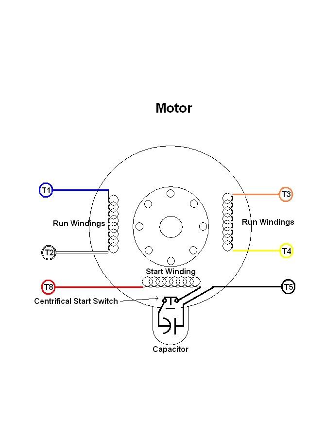
This makes it a little more complicated to hook up the drum switch but it is
very doable. Because the Black (T5) lead is connected internally, reversing the
motor's rotation will have to be done by reversing the RUN windings instead of
the START winding as is the usual practice.
I had made a specific diagram for your motor BUT Photobucket is having
issues at the moment and I cannot upload that diagram. (The motor diagram
was already uploaded). I will do my best to describe the connections.
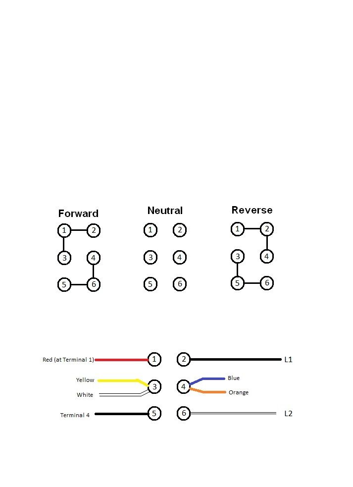
Using the numbering convention of the Dayton switch, the connections will
be as follows:
(1) - Connected to the #1 terminal at the motor's circuit board where the Red
motor lead goes (hook up the Red lead where it says to on the motor).
(2) - Connect the L1 Power lead.
(3) - Connect the Yellow and White motor leads.
(4) - Connect the Blue and Orange motor leads.
(5) - Connect to the #4 terminal at the motor's circuit board.
(6) - Connect the L2 Power lead.
If the motor turns the wrong direction, swap the leads a 1 and 5
at the drum switch.
Hopefully, Photobucket will get their act together and I can upload the
diagram and post a link.
Good Luck!
-Blue Chips-
Webb
The drum switch look like the old 2X440 (at least internal electrically).
That switch is perfectly capable of use on a single phase motor within
its amperage rating.
The Dayton motor is a little more unusual. It is a capacitor start, induction
run dual voltage motor but with a slight twist. It is very similar to this diagram
I have except the Black lead (T5) is connected internally to the phenolic circuit
board inside the motor where the electrical connections are made.
This makes it a little more complicated to hook up the drum switch but it is
very doable. Because the Black (T5) lead is connected internally, reversing the
motor's rotation will have to be done by reversing the RUN windings instead of
the START winding as is the usual practice.
I had made a specific diagram for your motor BUT Photobucket is having
issues at the moment and I cannot upload that diagram. (The motor diagram
was already uploaded). I will do my best to describe the connections.
Using the numbering convention of the Dayton switch, the connections will
be as follows:
(1) - Connected to the #1 terminal at the motor's circuit board where the Red
motor lead goes (hook up the Red lead where it says to on the motor).
(2) - Connect the L1 Power lead.
(3) - Connect the Yellow and White motor leads.
(4) - Connect the Blue and Orange motor leads.
(5) - Connect to the #4 terminal at the motor's circuit board.
(6) - Connect the L2 Power lead.
If the motor turns the wrong direction, swap the leads a 1 and 5
at the drum switch.
Hopefully, Photobucket will get their act together and I can upload the
diagram and post a link.
Good Luck!
-Blue Chips-
Webb
Re: lathe drum switch wiring
Webb, Thank you so much for taking the time to do this.. Does it matter on L1 and L2 which is the hot/black connection?
Also, the switch is in fact a 2x440..
John
Also, the switch is in fact a 2x440..
John
Re: lathe drum switch wiring
Hi There,
Typically, L1 is the Black (HOT) lead but in this application, it really doesn't
matter.
Good Luck!
-Blue Chips-
Webb
Typically, L1 is the Black (HOT) lead but in this application, it really doesn't
matter.
Good Luck!
-Blue Chips-
Webb
Re: lathe drum switch wiring
A special thanks again to Webb for figuring this out... Everything works as it should..
John
John
Re: lathe drum switch wiring
Hi There,
I'm glad I was able to help.
Finally, I got the wiring diagram uploaded to Photobucket.
I know it is moot for this applicant but others that may
want to see it, I have included here.
Good Luck!
-Blue Chips-
Webb
I'm glad I was able to help.
Finally, I got the wiring diagram uploaded to Photobucket.
I know it is moot for this applicant but others that may
want to see it, I have included here.
Good Luck!
-Blue Chips-
Webb