3D Code for Slanted/ Round Step?
Moderator: Harold_V
3D Code for Slanted/ Round Step?
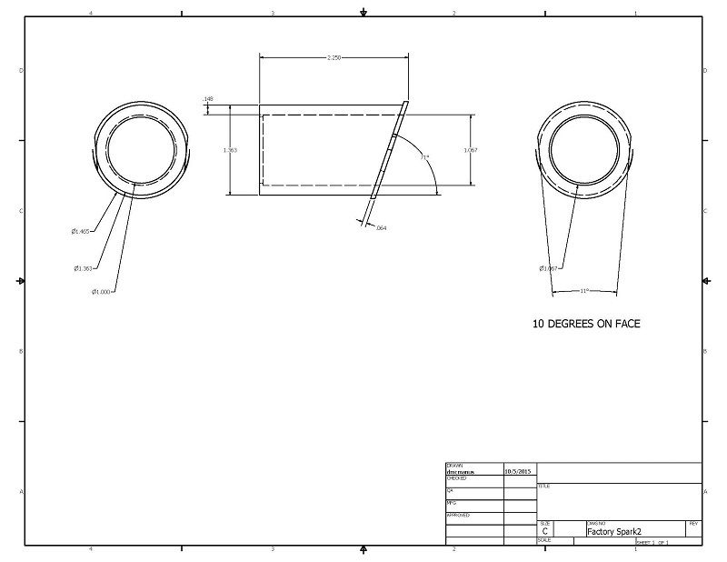
I would like to make the part in the drawing but that angled step is a problem. It seems like I could mount it flat end up and have the CNC cut the OD down to the angled step. I have access to a Bridgeport with Mach3 controller. The only CAM software is sheetcam which can not create that shape. Are there any code generators available that could generate that path? Are there any instructions or guidelines on line that would help to program it manually? Worst case it seems like it could be done in point to point mode but the math may be pretty challenging. Any recommendations?
Re: 3D Code for Slanted/ Round Step?
I looked at some references and this looks like helical interpolation that can be done with G02 and G03. However, the math looks pretty complex. It seems that the center of the radius is different in XY and XZ so I don't see how that is handled. Could a thread milling routine with standard end mill do this? ....Starting at the high point and going 180 degrees right handed, restart and go 180 degrees left handed with a TPI calculated to match that slope.

Re: 3D Code for Slanted/ Round Step?
It's the bottom side of the flange that can't be cut with a three axis mill.
That's one of those parts that was designed by someone that doesn't operate machines!
That's one of those parts that was designed by someone that doesn't operate machines!
Glenn
Operating machines is perfectly safe......until you forget how dangerous it really is!
Operating machines is perfectly safe......until you forget how dangerous it really is!
Re: 3D Code for Slanted/ Round Step?
It is a replacement for a cast part. If I can cut that 1.363 diameter down to an angled step, everything else is easy. With the flat end (left view on the drawing) facing up, this is cutting the diameter plus interpolation in z to get the angle.

Re: 3D Code for Slanted/ Round Step?
I think if there were a saw blade sufficient to clear the part, and with the profile of the acute angle of the flange to the cylinder wall. (or make a fly cutter)
Mount the stock at the angle to machine the face of the flange, but leave a rectangle boss just a hair smaller than the bore. This so you can flip the part over and clamp the boss with the flange in horizontal plane.
The saw will come in and run a circle to cut the flange and final diameter at the shoulder. Run a circle in x-y while moving x along with z up in tandem to cut the final diameter.
Flip part straight up and bore. Then cut the flats.
Will that work?
Standards are so important that everyone must have their own...
To measure is to know - Lord Kelvin
Disclaimer: I'm just a guy with a few machines...
To measure is to know - Lord Kelvin
Disclaimer: I'm just a guy with a few machines...
Re: 3D Code for Slanted/ Round Step?
Hi,
One way is to use a conventional lathe and a rotary table with the axis horizontal. Machine and bore the inside on a conventional lathe then transfer to the CNC mill and use "X" and "Z" in combination with the "A" axis to machine the outside diameter where the angled "washer" attaches to the cylinder. You can even do the "flats" this way.
That is how I would do it since I have the rotary headstock I would need (built it) and I can drive the "A" axis with the Sherline software. Yes it is doable, but it would be a bit slow because you would likely have to use a 3/16" cutter for a lot of it. Since it replaces a casting, a little departure from the drawing may be tolerated.
Richard Trounce.
Re: 3D Code for Slanted/ Round Step?
RET, I think that could work too, if you used a cutter like a dovetail cutter. I'm not sure how hard it would be to make the flange flat.
Standards are so important that everyone must have their own...
To measure is to know - Lord Kelvin
Disclaimer: I'm just a guy with a few machines...
To measure is to know - Lord Kelvin
Disclaimer: I'm just a guy with a few machines...
Re: 3D Code for Slanted/ Round Step?
The flange is mostly a retaining feature so would noo have to be perfectly flat.
Re: 3D Code for Slanted/ Round Step?
Hi,
A dovetail cutter won't work because the undercut angle changes as the part is rotated. A standard cutter is better even if it undercuts on the top and doesn't cut enough at the bottom. To get the angle, you rough saw it before putting it in the CNC machine and finish cut with a long end mill across the face.
Another and probably better method is to first use a regular lathe to machine the inside and outside of the part. Next, cut and mill the angle on the part, then silver solder a 1/16" thick "washer" on the angled face. Finally, finish bore and turn the washer. That way you don't need CNC at all unless you want to use it for the flats on the washer. This way has the added bonus of exactly replicating the drawing.
You don't always need CNC, sometimes traditional methods are just as good.
Richard Trounce.
Re: 3D Code for Slanted/ Round Step?
If a dovetail cutter wont work, then neither will a standard cutter, unless the angel is disregarded... I cannot see how to make the cut with a standard cutter!RET wrote:Hi,
A dovetail cutter won't work because the undercut angle changes as the part is rotated. A standard cutter is better...
Richard Trounce.
Standards are so important that everyone must have their own...
To measure is to know - Lord Kelvin
Disclaimer: I'm just a guy with a few machines...
To measure is to know - Lord Kelvin
Disclaimer: I'm just a guy with a few machines...
Re: 3D Code for Slanted/ Round Step?
The above won't work either. You'd have to run an ellipse rather than a circle.ctwo wrote:I think if there were a saw blade sufficient to clear the part, and with the profile of the acute angle of the flange to the cylinder wall. (or make a fly cutter)
Mount the stock at the angle to machine the face of the flange, but leave a rectangle boss just a hair smaller than the bore. This so you can flip the part over and clamp the boss with the flange in horizontal plane.
The saw will come in and run a circle to cut the flange and final diameter at the shoulder. Run a circle in x-y while moving x along with z up in tandem to cut the final diameter.
Flip part straight up and bore. Then cut the flats.
Will that work?
Standards are so important that everyone must have their own...
To measure is to know - Lord Kelvin
Disclaimer: I'm just a guy with a few machines...
To measure is to know - Lord Kelvin
Disclaimer: I'm just a guy with a few machines...
Re: 3D Code for Slanted/ Round Step?
I spent some more time and it looks like Mach3 can do this on its own. I used the thread milling wizard to create the helical interpolation. The cut down diameter can be the minimum thread diameter and the angle can be converted to TPI. Using a standard end mill, a right had thread and left hand thread can be cut. The cuts start at the bottom so the low points should match. It looks good running in air.
I can do the other features manually as second operations.
I can do the other features manually as second operations.