3D Code for Slanted/ Round Step?
Moderator: Harold_V

Re: 3D Code for Slanted/ Round Step?
I can't visualize it. How is the part held, as shown? And cut with a small EM?
Standards are so important that everyone must have their own...
To measure is to know - Lord Kelvin
Disclaimer: I'm just a guy with a few machines...
To measure is to know - Lord Kelvin
Disclaimer: I'm just a guy with a few machines...
Re: 3D Code for Slanted/ Round Step?
It can be held vertically in a mill vise with the small diameter/ non angled end up. Probably with a v block in the vise. The end mill will come down from the top and cut the 1.363 diameter OD. The helical interpolation will produce the angle at the bottom.
Re: 3D Code for Slanted/ Round Step?
Hi,
Yes it can be done that way, but you are still going to wind up with a part that doesn't have the undercut on the short side or the proper angle on the long side.
For the use your are going to make of it, that probably doesn't matter, but the only way I can see of reproducing the part exactly like the drawing is by silver soldering a washer on after the part is turned by conventional methods. No CNC is necessary in that case.
I have both capabilities and I use the machining method which makes the most sense for what I'm doing.
Just my take on things.
Richard Trounce.
Re: 3D Code for Slanted/ Round Step?
It cut but has an odd transition.

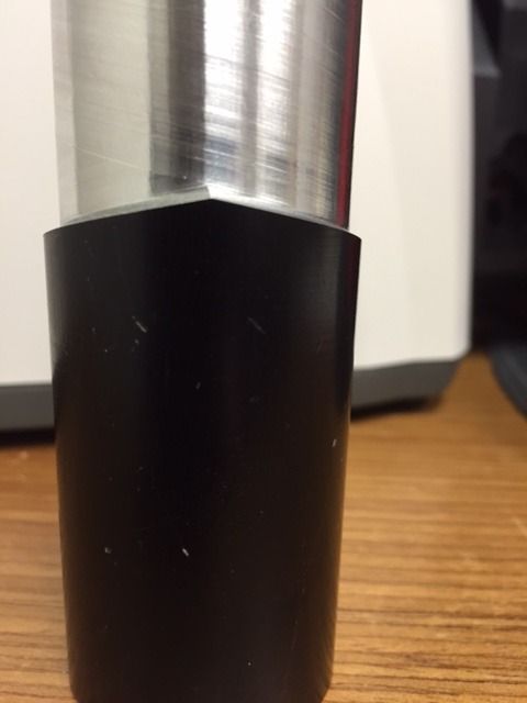
It seems like I could edit the code such that it was just one sweep around but I don't know if it would be any different.
One sweep
X1.69775 Y-0.503125
G00 Z-2.615
G01 G42 P0.4375 X1.194625 F20
G02 X0.6915 Y0 R0.503125
G03 X-0.6915 Y0 R0.6915 Z-2.1442
G03 X0.6915 Y0 R0.6915 Z-2.615
G02 X1.194625 Y0.503125 R0.503125
G01 G40 X1.69775
G00 Z0.1
M5 M9
Part machine from Thread wizard code like this
(conventional - leave .010)
G0 G49 G40 G17 G80 G50 G90
M6 T1 (TOOL DIA. 0.875)
G20 (Inch)
M03 S0
G64
G00 G43 H1 Z0.1
(Right hand OD Conv)
(WARNING THis is going To RAPID down to Z-2.615)
X1.69775 Y-0.503125
G00 Z-2.615
G01 G42 P0.4375 X1.194625 F20
G02 X0.6915 Y0 R0.503125
G03 X-0.6915 Y0 R0.6915 Z-2.1442
G03 X0.6915 Y0 R0.6915 Z-1.6734
G03 X-0.6915 Y0 R0.6915 Z-1.2026
G03 X0.6915 Y0 R0.6915 Z-0.7318
G03 X-0.6915 Y0 R0.6915 Z-0.261
G02 X-1.194625 Y-0.503125 R0.503125
G01 G40 X-1.69775
G00 Z0.1
M5 M9
(left hand + .01)
G0 G49 G40 G17 G80 G50 G90
M6 T1 (TOOL DIA. 0.875)
G20 (Inch)
M03 S0
G64
G00 G43 H1 Z0.1
(Left hand OD Climb)
(WARNING THis is going To RAPID down to Z-2.615)
X1.69775 Y0.503125
G00 Z-2.615
G01 G41 P0.4375 X1.194625 F20
G03 X0.6915 Y0 R0.503125
G02 X-0.6915 Y0 R0.6915 Z-2.1442
G02 X0.6915 Y0 R0.6915 Z-1.6734
G02 X-0.6915 Y0 R0.6915 Z-1.2026
G02 X0.6915 Y0 R0.6915 Z-0.7318
G02 X-0.6915 Y0 R0.6915 Z-0.261
G03 X-1.194625 Y0.503125 R0.503125
G01 G40 X-1.69775
G00 Z0.1
M5 M9
(to size)
G0 G49 G40 G17 G80 G50 G90
M6 T1 (TOOL DIA. 0.875)
G20 (Inch)
M03 S0
G64
G00 G43 H1 Z0.1
(Right hand OD Conv)
(WARNING THis is going To RAPID down to Z-2.615)
X1.68775 Y-0.503125
G00 Z-2.615
G01 G42 P0.4375 X1.184625 F20
G02 X0.6815 Y0 R0.503125
G03 X-0.6815 Y0 R0.6815 Z-2.1442
G03 X0.6815 Y0 R0.6815 Z-1.6734
G03 X-0.6815 Y0 R0.6815 Z-1.2026
G03 X0.6815 Y0 R0.6815 Z-0.7318
G03 X-0.6815 Y0 R0.6815 Z-0.261
G02 X-1.184625 Y-0.503125 R0.503125
G01 G40 X-1.68775
G00 Z0.1
M5 M9
G0 G49 G40 G17 G80 G50 G90
M6 T1 (TOOL DIA. 0.875)
G20 (Inch)
M03 S0
G64
G00 G43 H1 Z0.1
(Left hand OD Climb)
(WARNING THis is going To RAPID down to Z-2.615)
X1.68775 Y0.503125
G00 Z-2.615
G01 G41 P0.4375 X1.184625 F20
G03 X0.6815 Y0 R0.503125
G02 X-0.6815 Y0 R0.6815 Z-2.1442
G02 X0.6815 Y0 R0.6815 Z-1.6734
G02 X-0.6815 Y0 R0.6815 Z-1.2026
G02 X0.6815 Y0 R0.6815 Z-0.7318
G02 X-0.6815 Y0 R0.6815 Z-0.261
G03 X-1.184625 Y0.503125 R0.503125
G01 G40 X-1.68775
G00 Z0.1
M5 M9
M30

Re: 3D Code for Slanted/ Round Step?
I've been confused by your intended cut from the first day I looked. Now I see why. What you want to generate is NOT a helix, but a straight cut. They are not the same thing.
You will not be able to generate that tool path, as the end mill will constantly generate a 90° cut. As drawn, the cut is ever changing in relationship with the sides.
You might consider making the part in two pieces, which would eliminate having to create the changing angle of the cut.
Harold
You will not be able to generate that tool path, as the end mill will constantly generate a 90° cut. As drawn, the cut is ever changing in relationship with the sides.
You might consider making the part in two pieces, which would eliminate having to create the changing angle of the cut.
Harold
Wise people talk because they have something to say. Fools talk because they have to say something.