First CNC project near completion!

This forum is dedicated to those Hobbyists Interested in CNC machining & 3D Printing in their home shops. (Digital Read Outs are also topical, as is CAD/CAM as it relates to CNC)

Moderator: Harold_V

Holescreek
Posts: 67
Joined: Mon Dec 17, 2007 7:28 pm
Location: Centerville, OH

First CNC project near completion!

Post by Holescreek »

A while back my uncle decided to leave northern OH for sunny FL and gave me the contents of his home shop. Among the tons of tooling and machinery was a well used Enco (RongFu 30) mill and I really didn't need another manual mill.
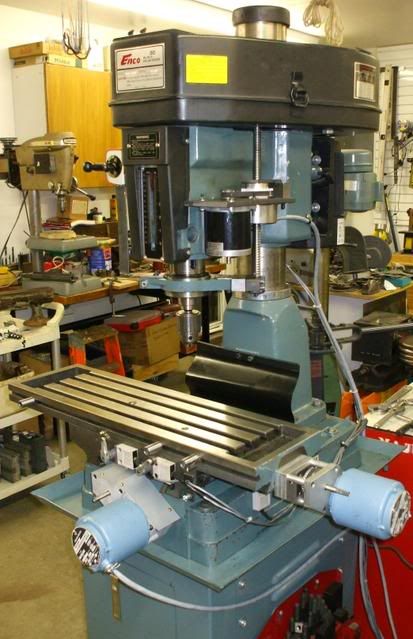
I spent a couple hundred hours (seems like) on the net researching the current methods and decided to design and fabricate my own conversion parts. I started by blueprinting the entire bottom end of the mill and shopping for motors and drive components. I got the belts and pulleys from econodrive and just about everything else from Ebay. (My starting goal was to complete the retrofit for <$800.)
I usually save the large projects for winter when I don't feel guilty for spending lots of time in my shop. Last winter the mechanicals were completed, this winter was the electronics and I'm just finishing up the 4th axis horizontal rotary table.
Image
Image
Image
Image[/img]
Image

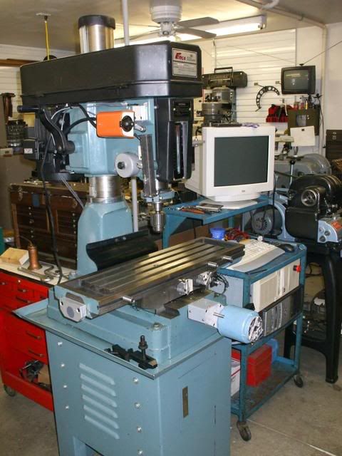
Anyone else using a 4th axis? If so, what for?

-Mike
RET
Posts: 960
Joined: Wed Jun 07, 2006 8:36 am
Location: Toronto, Canada

Post by RET »

Hi Mike,

The little Sherline CNC mill I have has a rotary table as a 4th axis & I've used it for a couple of jobs. The first "G" code programming I did was to mount the table on its side & write a simple program to cut hex heads on standard socket hd. cap screws. Turned out to be quite useful since the capscrews are hardened (but not so hard that HSS cutters won't cut them). This gave me hard hex hd. bolts that wouldn't break the first time I looked at them sideways.

The second time I've used it was to cut the pockets on the pelton wheel blanks for a turbogenerator. Again, the code was quite simple, but having the table made a boring, tedious hand operation into something simple & reliable.

Remember, if there is no code for the extra axis ("A"), it doesn't do anything so it isn't even neccessary to disconnect the table unless you want to.

Bottom line is you never know what you may wind up using the table for. If you have it, its certain that it will come in handy in ways you can't even predict ahead of time.

Richard Tounce.
Holescreek
Posts: 67
Joined: Mon Dec 17, 2007 7:28 pm
Location: Centerville, OH

Post by Holescreek »

Richard,

I am wanting to do some helical grooving on another project. I haven't dug deep enough into the G codes to figure out which will give me simultaneous movement in X while A is rotating. The 4th axis setup should also minimize the number of times I have to set up the dividing head on my Bridgeport for those odd hex jobs that come up from time to time. The first A axis I'm building is pretty small, I have a 4" 3-jaw chuck being turned by a 125 oz/in stepper. If it all works out I might just convert aH/V rotary table.

Thanks for the input. -Mike
User avatar
Bill Shields
Posts: 10560
Joined: Fri Dec 21, 2007 4:57 am
Location: 39.367, -75.765
Contact:

Helical

Post by Bill Shields »

the standard practice for that type of move (varies a bit with machine to machine), is to program the linear and rotary moves all on one axis.

So you have something like:

Xxxx Aaaaa Ffff

X=linear
A=rotary
F=feed

Keep in mind with this sort of programming that the end points will both be reached at the same time, so the X and A actual speed will vary, so be careful....if your linear feed is TOO HIGH, the rotary axis may not be able to keep up...

Capice?
Holescreek
Posts: 67
Joined: Mon Dec 17, 2007 7:28 pm
Location: Centerville, OH

Post by Holescreek »

Bill, I kind of remember reading something about it in the mach3 mill manual. I read it over a period of a month or so during breaks and lunch at work. If I remember correctly, Mach adjusts the speed of all axis on one line of code to the speed of the slowest axis so that they all end at the same time. The A axis is complete mechanically, I am wiring the cables to the control plugs tonight and am waiting for another Gecko to arrive to finish it off. I'll find out soon enough. -Mike
User avatar
Bill Shields
Posts: 10560
Joined: Fri Dec 21, 2007 4:57 am
Location: 39.367, -75.765
Contact:

speeds

Post by Bill Shields »

Exactly....
Holescreek
Posts: 67
Joined: Mon Dec 17, 2007 7:28 pm
Location: Centerville, OH

Post by Holescreek »

I ran my first fully CNC program yesterday and everything went as planned. A good friend needed some parts to adapt an older bed frame to a new wider mattress. I stacked two plates together and tack welded the edges so that I'd get a pair of parts from each cut.

Image
Image
Image
Image

Hopefully the Gecko I ordered for the A axis will arrive shortly and I can get it moving soon.
User avatar
Bill Shields
Posts: 10560
Joined: Fri Dec 21, 2007 4:57 am
Location: 39.367, -75.765
Contact:

CNC

Post by Bill Shields »

Just be careful of the round column that can allow the head to move relative to the table....when you least expect it

Without the 'feel' in the handles....you can sometimes push (esp with a dull cutter) a lot harder than you might have with a hand wheel....
Holescreek
Posts: 67
Joined: Mon Dec 17, 2007 7:28 pm
Location: Centerville, OH

Post by Holescreek »

Bill,
Yes the round column wouldn't have been my first choice but the price was right. I am considering making a two-rod guidance system which would connect to the head at the top and base at the bottom where the rods would hold the alignment of the column when raising and lowering the head. -Mike
User avatar
Bill Shields
Posts: 10560
Joined: Fri Dec 21, 2007 4:57 am
Location: 39.367, -75.765
Contact:

Alignment

Post by Bill Shields »

M:

Unless the rods are VERY LARGE, they really won't hold much alignment that would be worth counting on.

As long as you are aware of the problem, you should be alright.

One thing that I recommended to a fellow a while back is to use a dial indicator mounted on the head, touching an 'indicator plate' that runs alongside the column...sort of like an alignment bar we used to use on big machinery to measure thermal growth as equipment came up to operating temperature.

This will allow you to zero the indicator when you start cutting, and IF IT MOVES - indicating that the head has rotated on the column - you know that the part isn't going to be expected.

Doesn't stiffen the machine, but at least tells you when you are headed for trouble....and time to slow down or get a sharper cutter... :shock:
Jose Rivera
Posts: 3803
Joined: Wed Feb 21, 2007 9:21 pm
Location: Vallejo California

First cuts

Post by Jose Rivera »

I get goose bumps seeing parts clamped right into the table Holescreek :-)

I see already a tool mark on one of the pictures.

Is there a reason why you're setting up so close to you working table?

Just curious.

Putting a tool mark in a mill table was grounds to loose your job during my active time.
Wonder if this rule has changed.
Holescreek
Posts: 67
Joined: Mon Dec 17, 2007 7:28 pm
Location: Centerville, OH

Post by Holescreek »

Jose, I know what you mean when it comes to table marks. Since my uncle was kind enough to give me the mill I wasn't about to berrate him over a couple of drill throughs. The parts are in fact not clamped directly to the table but are sitting on paralells. Hard to see in the photos I posted but there was plenty of room for the parts to drop through when the cut finished. If you look closely at the photo below you can see the height difference between the bottom of the clamps and the top of the table.

Good thing to point out though, I keep forgetting that everyone hasn't been doing this for 26 years already. :mrgreen: -Mike
Image
Post Reply