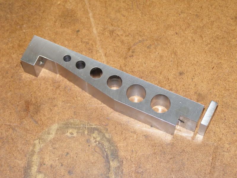
I made it from A2 tools steel and heat treated and tempered it to 60RC. I thought I had taken more pics of the process, but I guess not. I was making a 5" bar at the same time that I have not yet completed and was trying to take pics of both. Here's the 5" bar roughed out prior to heat treating.
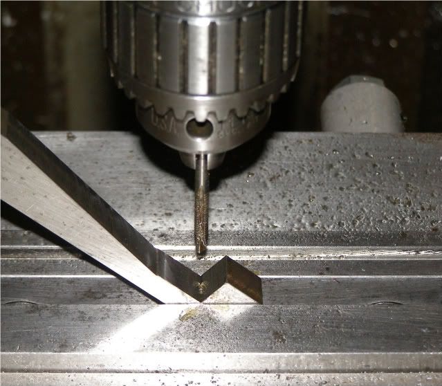
Back to the small bar. In the mill drilling and tapping the holes for the "wheels".
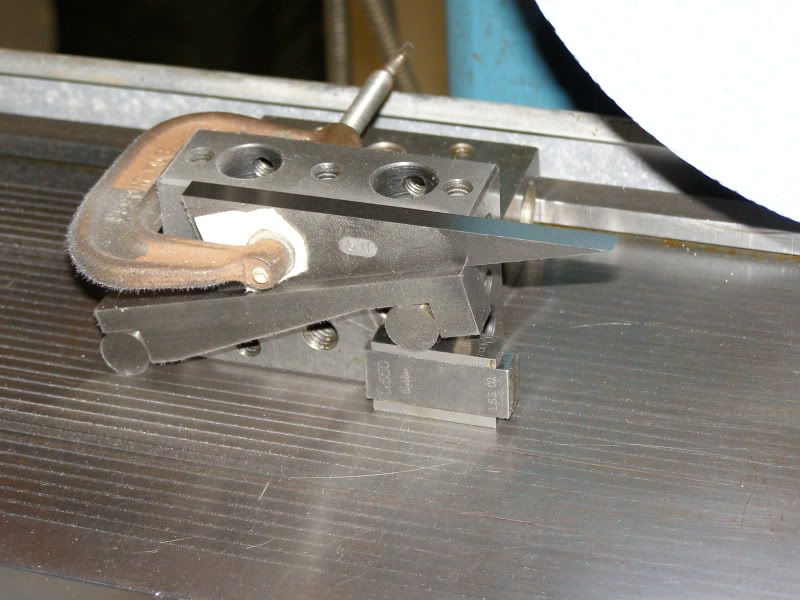
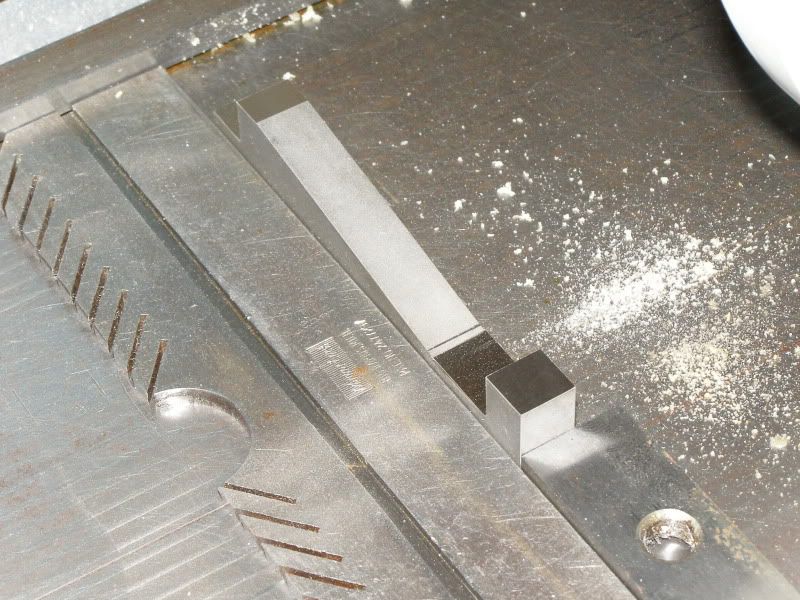
After heat treating, the start of the grinding process. I ground the upper surface first as a reference surface. Then flipped it over, indicated one side parallel to the Z axis, and then ground the lower side and the "wheel" spacing shoulders. I bolstered it in place to lessen the chance of it moving on the chuck.
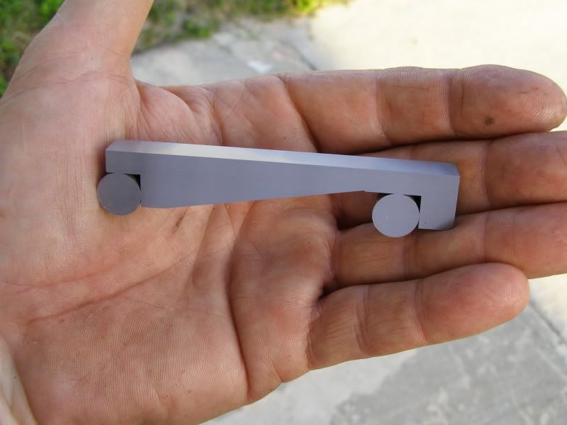
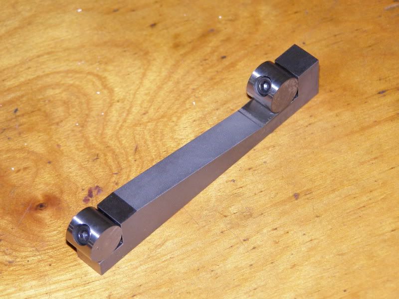
This is a pic of it with the wheels installed for center to center distance insoection prior to any further grinnding. This also shows how the "wheels" are attached.
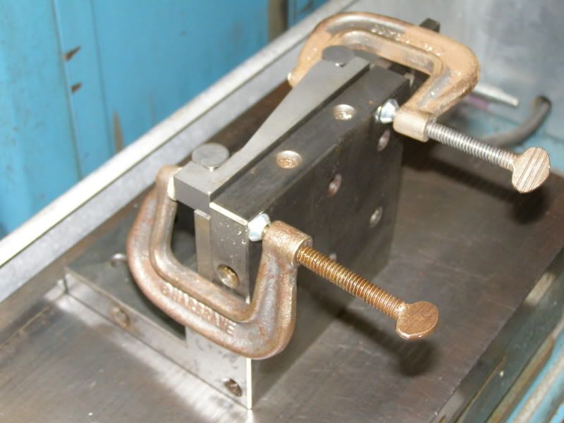
Next was to clamp it to a precision step angle plate. The upper surface in this pic is the same surface I indicated in the previous pic. I indicated this surface parallel with the chuck and ground it.
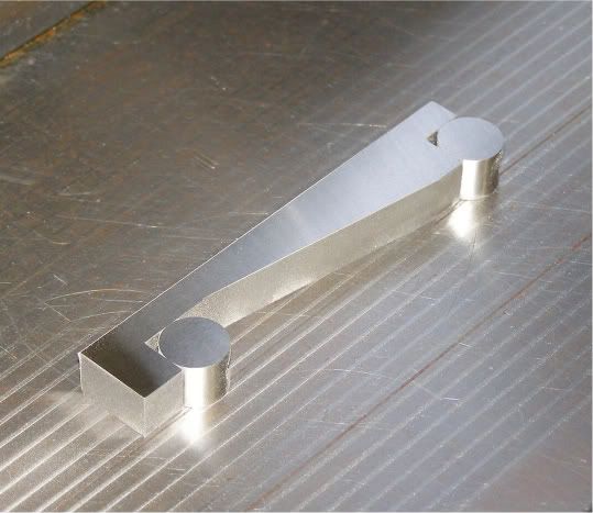
Next it was flipped over and stuck to the chuck for grinding the other side parallel and square.
Next was to grind the ends square using the angle plate. . Don't have pics of that process...
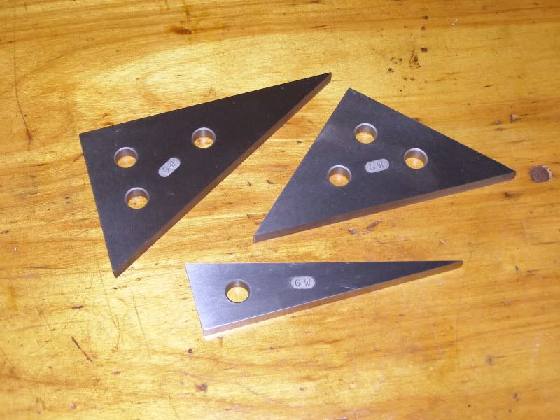
It came in handy for the next project...
Thanks!