Hi There,
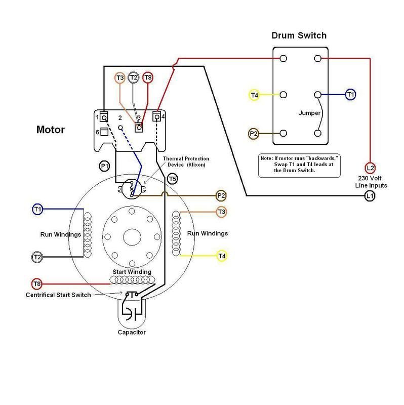
race5050 wrote:wlw... Yes, the motor plate says its "Thermally Protected Auto". I believe your right about the internal hard wire. I have the schematic provided by grainger but noticed one terminal is not accessible. When I thought it through, it wasn't making sense to alternate only one start winding since two are shown in the motor schematic. Logically it makes sense to then alternate both main windings, but I can't figure out how to do that with the funky connection pattern of my drum switch. I'll buy another switch if I have to. I'll post the motor schematic from grainger later tonight when I get home.
Thx!
That would be helpful but I should be able to help without it.
But, I need to know what voltage you are planning to use.
The 'funky' part is taking advantage of the thermal overload
protection built into the motor. By the way, I'm not a big fan
of 'Auto' reset motors used on lathes. The reason is that IF
the motor overloads and trips the device, the operator may
forget to turn off the lathe and after it cools down, the motor
resets and the lathe starts up by itself; not exactly the 'safest'
thing when dealing with potentially hazardous machinery. It
should be okay so long as one remembers to turn off the
machine after it 'trips' the thermal device.
Good Luck!
-Blue Chips-
Webb
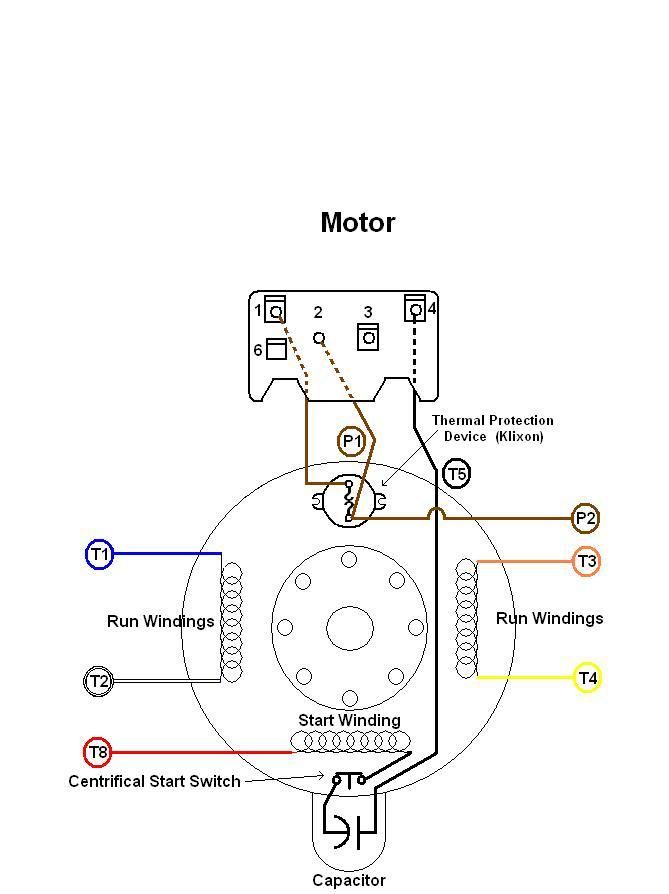
Edit: Here is a diagram of the motor (as I see it) showing the internal wiring: