Building the gingery metal mill

Home enthusiasts discuss their Foundry & Casting work.

Moderator: Harold_V

norman
Posts: 50
Joined: Tue May 18, 2010 5:16 pm

Building the gingery metal mill

Post by norman »

I have the shaper done, I've used the shaper on machining the mill bases and the bottom of the head stand.
Gadjet is all ready making the mill so some of these photos will look kind of the same. I started this project about the middle of July. Started 7-21-2010.

Image

Image
The bed has a small void where I cut off the pouring gate. Instead of making the 2 bases 1/4" thick I made them 1/2" thick.
I had to cast the head stand twice the first one had a bad void at it's base.
Image
I have the ways installed, the bases bolted to the bed, so now its on to making more patterns. Next is the head stand spindle Gadjet says there is a problem with the dimensions on the head stand?
If your looking at my mess Gadjet could you clue me in before I start cutting wood.
Norman
User avatar
Harold_V
Posts: 20248
Joined: Fri Dec 20, 2002 11:02 pm
Location: Onalaska, WA USA

Re: Building the gingery metal mill

Post by Harold_V »

norman wrote:Instead of making the 2 bases 1/4" thick I made them 1/2" thick.
A good choice. You will never regret adding rigidity to any machine tool.

Looking good so far!

Harold
Wise people talk because they have something to say. Fools talk because they have to say something.
Gadget
Posts: 61
Joined: Thu Dec 24, 2009 9:02 pm
Location: Michigan

Re: Building the gingery metal mill

Post by Gadget »

Norman,
The spindle bearing part of the vertical slide dimension should be 3" not 4". This is on page 66 of the book. I have attached a photo of the prints with the corrected dimension. There needs to be one inch of the spindle slide below the bearing pad for the clamp bolt.
Dan
Attachments
corrected dimension.
norman
Posts: 50
Joined: Tue May 18, 2010 5:16 pm

Re: Building the gingery metal mill

Post by norman »

Thanks! Gadjet
I found that problem yesterday. I was watching for a problem and that is what I found the 4" should have been 3" so I went ahead and made the part 3" hoping that was what you had found to be wrong as well.
I'm plunking away at the patterns. I skipped the hand wheels for now and I've gotten the patterns done up to page 85 the work table support pattern. I'll go back and make the patterns for the hand wheels tomorrow or start casting the patterns I now have made.
thanks again.
Norman
Last edited by norman on Mon Aug 02, 2010 11:14 am, edited 1 time in total.
Gadget
Posts: 61
Joined: Thu Dec 24, 2009 9:02 pm
Location: Michigan

Re: Building the gingery metal mill

Post by Gadget »

At that rate Norman you may finish before I do. I have been mired down lately with painting the house. Once that's done I'm free to blast ahead though.
Dan
norman
Posts: 50
Joined: Tue May 18, 2010 5:16 pm

Re: Building the gingery metal mill

Post by norman »

Past few day I've been making more patterns.
I have the patterns all made up to page 129.
This thing has a lot of small parts. Some patterns use interchangeable parts, there is going to be a lot of sand pounding to get it done.
Image

Image
These are the latest patterns made. the middle photo has one side of the patterns, this photo shows the other side of the patterns, some of them with the split parts laid out beside or next to it's mate. Only about 6 to 8 more patterns to make I think?
Image

Norman
Gadget
Posts: 61
Joined: Thu Dec 24, 2009 9:02 pm
Location: Michigan

Re: Building the gingery metal mill

Post by Gadget »

Nice work there Norman. I've been building my patterns as I need them. Some of them were CNC cut in lost foam and destroyed in the pouring process but I still have the machine code to create new ones if needed.
Dan
norman
Posts: 50
Joined: Tue May 18, 2010 5:16 pm

Re: Building the gingery metal mill

Post by norman »

Here is the latest casting did last night.
Fresh out of the sand only the small aluminum wires that form from the venting process have been removed.
Image
Now I'll cast the other half of the spindle slide and more small parts
They don't look all that nice but they turned out fine.
Gadget
Posts: 61
Joined: Thu Dec 24, 2009 9:02 pm
Location: Michigan

Re: Building the gingery metal mill

Post by Gadget »

They look good to me Norman.
I cast the bearing cap for the compound swivel today, it turned out well.
Dan
norman
Posts: 50
Joined: Tue May 18, 2010 5:16 pm

Re: Building the gingery metal mill

Post by norman »

Photos of the parts that were cast yesterday. Cleaned up ready to start some machining.
one side
Image
the other side
Image
here they are sitting on the mill where they go.
Image
norman
Posts: 50
Joined: Tue May 18, 2010 5:16 pm

Re: Building the gingery metal mill

Post by norman »

did more casting today here they are right out of the sand.
Image
got 3 done in one pour on this one.
Image
Last edited by norman on Fri Sep 10, 2010 10:34 am, edited 1 time in total.
norman
Posts: 50
Joined: Tue May 18, 2010 5:16 pm

Re: Building the gingery metal mill

Post by norman »

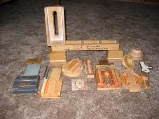
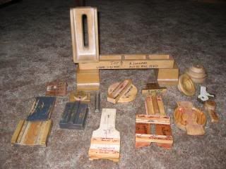
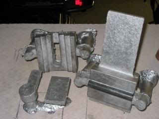
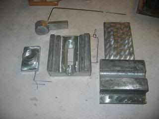
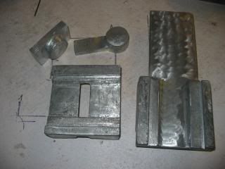
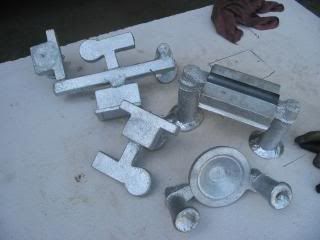
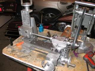
Here is the latest on the mill. The slides are done,the parts to bore the spindle are cast and done. I'm now in the process of boring the spindle so here's some photos of that.
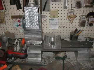
the mill is set up to bore it's spindle head. I'm using the drive system off of the shaper to power the boring bar. I should have used 3/4" plywood to mount this as the 1/2" is too thin and makes the drive system sag so being a red neck builder I'm using my face plate for support under the drive system. I may change the plywood to 3/4" before I finish the boring.
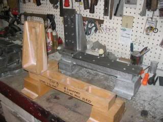
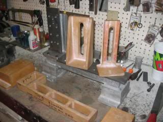
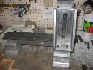
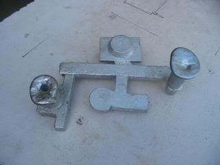
Image
Quill support.
the plans say to slit one side of the bronze bushing for the the bearing for this. I didn't want to do that so I made a right angle plate to mount to my face plate and bored the quill support. I pinned the bushing to lock them in place sort of how a vw engine main bearings are locked in place so they won't spin in the block.
I did about 3 to 4 hours of run in on the bearings with a little sewing machine motor mounted to spin the shaft, lot of oiling of the bearing during wear in.
Image
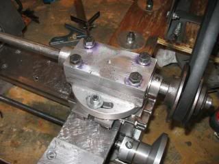
the plans call for using a square bit to bore with, again being lazy I'm using a bit made from 1/4" drill rod no need to make a square hole to mount the bit. It works good for me.
Image
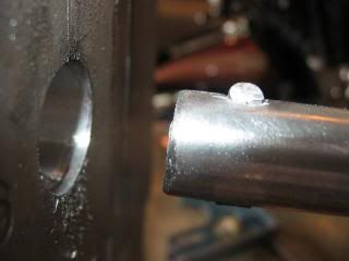
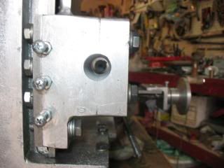
view through the spindle head after 2 passes with the boring bar.
I need to open this up to about 1.124 right now I'm close to .875

Image
Post Reply