Page 1 of 1
Sine Bar Project
Posted: Tue Jul 06, 2010 7:19 am
by GlennW
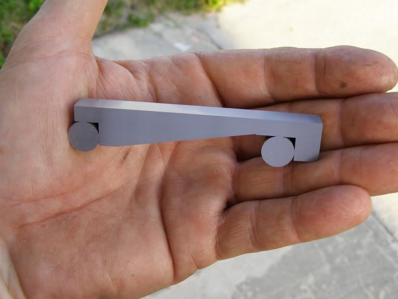
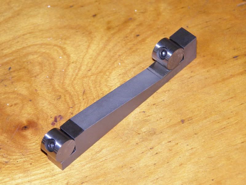
I thought a small Sine Bar might be handy, so I made a 3" size. It will work in my milling machine vise, and is just .010" wider than a rectangular gauge block.
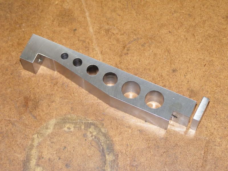
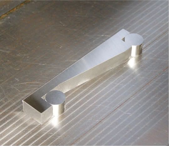
I made it from A2 tools steel and heat treated and tempered it to 60RC. I thought I had taken more pics of the process, but I guess not. I was making a 5" bar at the same time that I have not yet completed and was trying to take pics of both. Here's the 5" bar roughed out prior to heat treating.
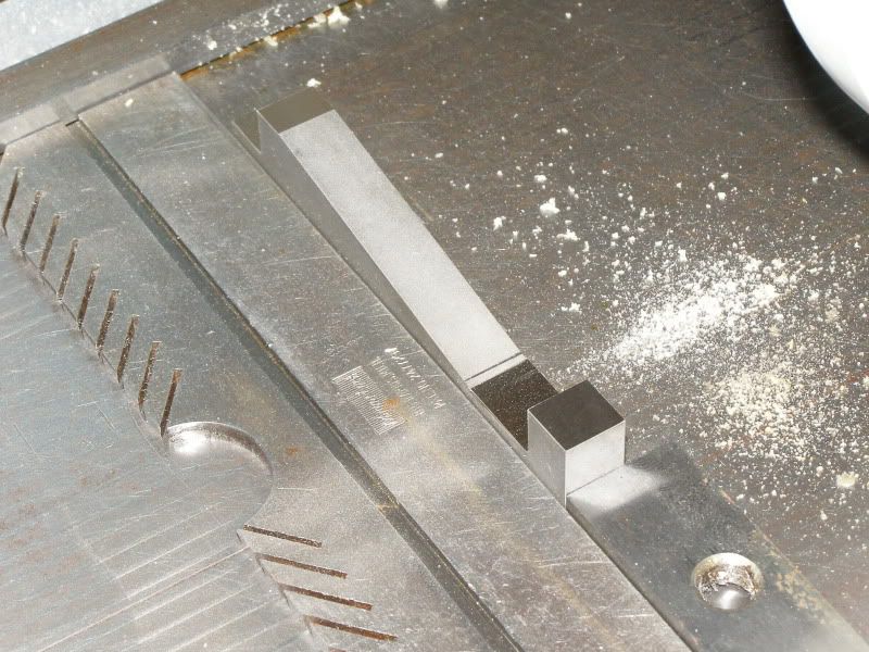
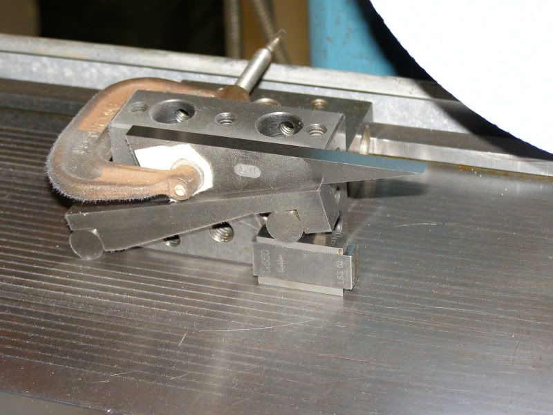
Back to the small bar. In the mill drilling and tapping the holes for the "wheels".
After heat treating, the start of the grinding process. I ground the upper surface first as a reference surface. Then flipped it over, indicated one side parallel to the Z axis, and then ground the lower side and the "wheel" spacing shoulders. I bolstered it in place to lessen the chance of it moving on the chuck.
This is a pic of it with the wheels installed for center to center distance insoection prior to any further grinnding. This also shows how the "wheels" are attached.
Next was to clamp it to a precision step angle plate. The upper surface in this pic is the same surface I indicated in the previous pic. I indicated this surface parallel with the chuck and ground it.
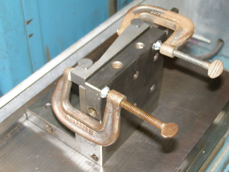
Next it was flipped over and stuck to the chuck for grinding the other side parallel and square.
Next was to grind the ends square using the angle plate. . Don't have pics of that process...
It came in handy for the next project...
Thanks!
Re: Sine Bar Project
Posted: Tue Jul 06, 2010 8:14 pm
by dly31
Nice work!
Don Young
Re: Sine Bar Project
Posted: Tue Jul 06, 2010 10:00 pm
by Marty_Escarcega
Very nice professional work Glenn
Marty
Re: Sine Bar Project
Posted: Wed Jul 07, 2010 8:47 am
by GlennW
Thanks Guys!
Re: Sine Bar Project
Posted: Wed Jul 07, 2010 1:41 pm
by Sleazey
Excellent work Glenn!
Can you tell me what techniques you used to get the spacing of the 2 right angle legs (where the rods are nestled)? That is the critical part of the sine bar.
Did you aim for a precise distance (like 5"), or did you accept what came out and the final measured spacing with cylinders becomes the base constant for this particular bar?
Thanks. This looks like a good little project for those with a surface grinder.
Re: Sine Bar Project
Posted: Wed Jul 07, 2010 5:35 pm
by GlennW
Sleazey wrote:Can you tell me what techniques you used to get the spacing of the 2 right angle legs (where the rods are nestled)? That is the critical part of the sine bar.
I cheated!

It is a metric machine that was previously fitted with a Imperial reading Sony DRO with Y,Z scales. I have not done much grinding that needed to be exact in both Y and Z, so it was a good project to play with. I didn't trust the DRO, as I had not had a chance to check it's accuracy, but I figured I'd give it a go.
Sleazey wrote:Did you aim for a precise distance (like 5"), or did you accept what came out and the final measured spacing with cylinders becomes the base constant for this particular bar?
I was looking for exactly 3".
I dressed the face and side of the wheel prior to grinding the "pockets" and rough ground them. I did another quick dress and just touched one face up, zeroed the DRO in Z, moved to the other, and touched it up until I had exactly 3", letting it "spark out" on both faces. I then dropped down a tenth and cleaned up the height staying just shy of the face.
I considered using gauge blocks and a DTI to make the move initially, but opted to "test" the DRO, as I figured if it was off a bit, it wouldn't be very much so i could fix it if needed. When I finished up that step, I screwed on the "wheels", placed the sine bar on the Jig Borer, which I use frequently for measuring, squared it up. and measured the spacing touching off with a DTI. I zeroed the dial, swept the first wheel vertically with the quill and zeroed the DTO, moved exactly 3" with the dial, and swept the second wheel and it was within a tenth. (I was quite surprised) I verified it a few times and then checked a 3" gauge block using a similar method to be sure.
The "wheels" were stuck together and OD ground as one, so they are exactly the same diameter.
Thanks!
Re: Sine Bar Project
Posted: Wed Jul 07, 2010 5:44 pm
by randyc
That is a HANDY size for normal vises - I've always felt that five inches was a tad long for most of us !
What Sleazey mentioned is a good thought, however. As long as the shoulders are parallel, the exact distance between the rolls isn't important - just measure the distance (center to center) precisely and stamp on the bar before heat treating and grinding. Then use that constant to multiply the sine of the desired angle to get the gage block stack.
Glen: just a thought: might want to grind a chamfer on the base leg so you can get a greater angle capability:

Cheers,
Randy
EDITED TO ADD: LOL, my bad - wasn't thinking too clearly when I posted earlier. All that's required is to flip the sine bar 180 degrees and there's no interference. Sorry !
Re: Sine Bar Project
Posted: Thu Jul 08, 2010 8:27 am
by GlennW
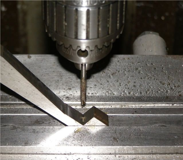
I needed the little Sine bar to accurately make the little triangles, which are unfinished. Also from A2 tool steel and heat treated to 60RC
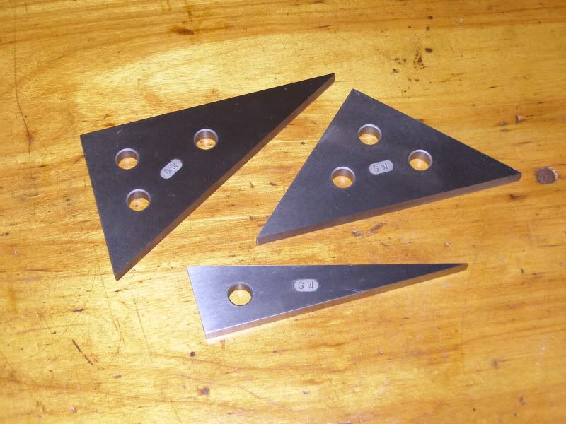
They come in handy on occasion for quick setups.
Re: Sine Bar Project
Posted: Thu Jul 08, 2010 7:10 pm
by chazc
Hi; Darn nice work- makes me want to go out and buy a grinder .
I don't know were I would put one,
chaz
Re: Sine Bar Project
Posted: Tue Jul 13, 2010 6:33 pm
by PixMan
Nice work, looks good.
I have my 5" sine bar that I made in vocational school back in 1975 or 76. I noticed one major difference between yours & mine, other than size. On mine, the counterbored clearance holes are through the body of the bar and the tapped holes are in the dowels, so you don't see anything but smooth & round on those pins.
I'll have to get over to my dad's shop and grab a photo. It's been in his box for about 20 years.

Re: Sine Bar Project
Posted: Wed Jul 14, 2010 6:53 am
by GlennW
I just felt it looked much cleaner without SHCS heads being visible on the upper surface to collect swarf. Being on the bottom, you don't see them during normal use, and they have no adverse affect on functionality.