Page 1 of 2
Mic-6 jig plate for the new rotab
Posted: Sat Oct 30, 2010 8:19 pm
by coal miner
Got started on the mic-6 jig plate for the new rotary table the last couple of days in between other things going on . Put the rough plate on the mill and drilled 4 -25/64" holes at 3 1/4 " radius and counter bored w/a 5/8" end mill to clear the shcs .
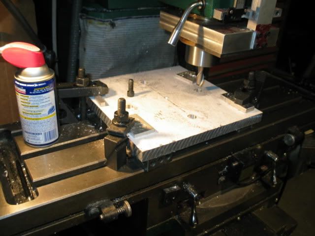
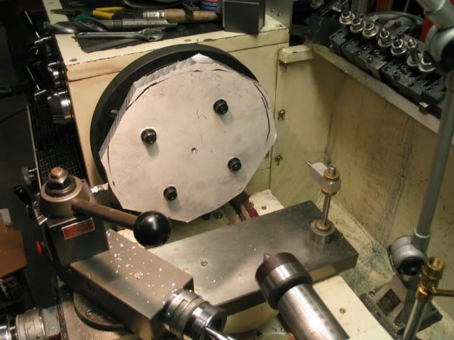
While the plate was on the mill also center drilled it for easier centering on the lathe w/ the tail stock . Got it over to the lathe to mount up and discovered that the face plate , which had never been used , had the the mounting studs all out of wack . After cleaning everything spotless found the locks would not close properly on two of them so had to take it back off and adjust the studs to the proper height . After getting it mounted on the spindle set up a DI and the face ran within a .001 , very surprised that the Chinese Jet was that close . Even rotated it 120º and it still ran with in a couple .001 . Good enough for me . Used the holes to mount the plate after butchering off the corners on the horizontal saw swung vertical . Not pretty , but will work for cleaning up the edge .
Crazy way to get clearance for the cutting tool and the carriage .
Finished out to 10 1/2 " and bored a .825 hole in the middle for a stub to mate to and set in the the 1.180 diam recess in the rotab .
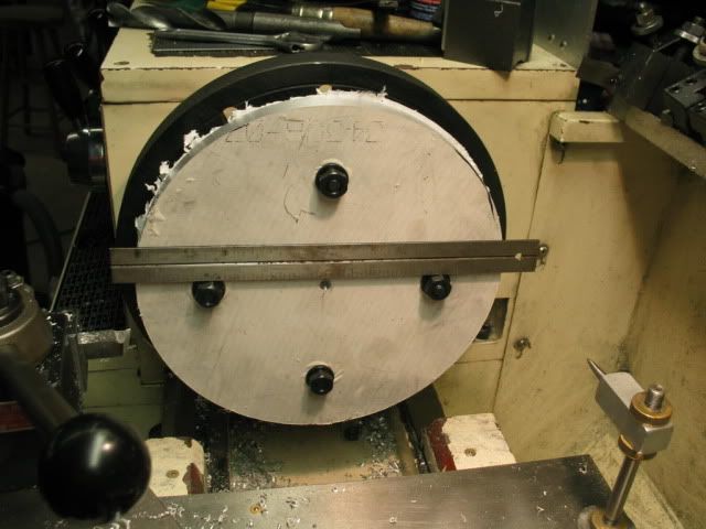
Had some 1.250 Al rod so used that to make the adapter that would go in the plate and center the plate to the rotab so if the jigplate is removed it should go back on and be concentric w / rotabs table .
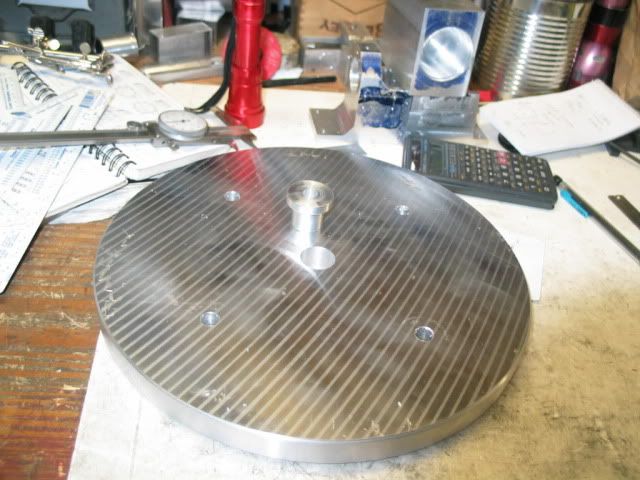
Both of the fits had a loose press fit LOL , so out came the locktite for the piece that went in the jigplate .
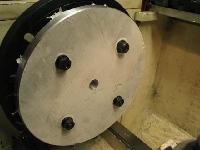
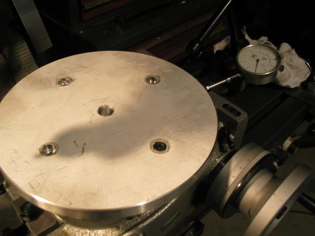
All mounted up and checked the run out by cranking the table around and was pleased that it was less than .0015 . Liker they say , A blind hog finds an acorn in the woods every once in a while . I really watched my P's and Q's on doing the measuring and thinking the steps thru on order of ops . One thing that I will do is thread the center hole so one can bolt thru the middle . Got a lot more holes to locate and drill and thread now . Any idea on a pattern ? Will incorporate concentric circles in 1" increments on it .
More to come , I hope .
Re: Mic-6 jig plate for the new rotab
Posted: Sat Oct 30, 2010 8:51 pm
by pockets
Awsome. A very useful project that even I can emulate.
Thanks,
Greg B.
Re: Mic-6 jig plate for the new rotab
Posted: Sun Oct 31, 2010 10:56 am
by 737mechanic
Coal miner, not sure if you saw the link I posted of Frank Fords rotary table plate in the rotary table thread. He did a great job of documenting everything he did. It might give you some ideas.
BTw so far everything looks good. where did you find the aluminum plate?
http://www.frets.com/HomeShopTech/Proje ... plate.html
Re: Mic-6 jig plate for the new rotab
Posted: Sun Oct 31, 2010 11:21 am
by EdK
coal miner,
Nice job on the plate. I'm still on the look-out for a chunk of aluminum for my RT.
Keep the pictures coming.

Ed
Re: Mic-6 jig plate for the new rotab
Posted: Sun Oct 31, 2010 4:09 pm
by coal miner
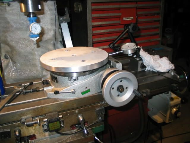
Got everything mounted and will check the tram to spindle in the x & y axis .After setting the mag DI on the spindle ,with the protective paper still on the top , I had .0025 out in the y-axis and .0015 in the x-axis by cranking the wheels . This is in 10.5 inches across the top and side to side of the plate. One thing on the y-axis , I didn't have the locks engaged .That means to me that the plate is at least paralell to the table to a certain degree . Will do a proper tram tomorrow , hopefully it won't be any worse . Don't know if this is close enough , but I think will suffice for my needs . Any critiques are welcome .
The plate was purchased from E- Bay vendor ssshapiro in St Louis , so shipping wasn't too much , only 90 mi . I still have some reservations about the 3/4`" thickness , maybe it should have been 1" . There was none listed except the place in Ca. It is what it is .Will get some more pics .
AS I said any ideas or criticisms accepted , I'm sure no expert and have the desire to learn from my mistakes .
Re: Mic-6 jig plate for the new rotab
Posted: Sun Oct 31, 2010 5:35 pm
by ken572
coal miner,
Very Nice job you have done.

(Food For Thought)
Maybe you could cross drill and tap 1/4"x28 or so, from the edge
of the plate into the X and the Y axis, aimed at each mounting
bolt on the plate. Snug the plate up with the mounting bolts, and
then with your 1/4"x28 set screws in your new edge holes you can
apply pressure where needed to eliminate all X, Y, runout. You can
then add a second set screw on top of each pusher set screw to lock
them in. (Don't forget the LOCK-TITE

)
At PDI., in Wisconsin we used to pull our hollow ground high speed
FamCo shear blades into a (ZERO GAP) with there pusher puller
adjusters that were on the shear beds, the same way.
Ken.
Re: Mic-6 jig plate for the new rotab
Posted: Sun Oct 31, 2010 6:48 pm
by coal miner
Maybe this question should go in another thread but........... on tramming the rotab plate properly (10.5 diam.) , I have .0015 difference on the plate mainly in the x-axis . All table locks on . I thought maybe I better check the mill table itself to make sure that it was ok . I have got a good cross hatch pattern using an end mill or a flycutter , so thought everything was fine . Trammed the mill table out as far as the Noga would reach ( around12.5 radius) and came up with.0035 out . I will try to get it closer tomorrow . Being a relative newcomer at this , what do you guys try to work to as far as this situation .
Ken , that's a good idea on the jack screws , but everything points to the table being pararell to the table , just a mite out of tram . Wonders never cease !
Re: Mic-6 jig plate for the new rotab
Posted: Sun Oct 31, 2010 9:12 pm
by GlennW
coal miner,
Check the tram on the RT, then rotate it 180°, and then check it again.
That will veriy that it is or is not the RT plate surface.
The mill table could be in tram by itself, but by adding the RT, the knee may be in a different position, and/or the weight of the RT may change it slightly.
Nice job on the plate!
Re: Mic-6 jig plate for the new rotab
Posted: Mon Nov 01, 2010 8:35 am
by coal miner
To all ,thanks for the compliments gentlemen . Making progress on proficiency at machining at least until an ,oh poop shows up , to bring me back down to my hack status . There is so many details that have to addressed , it taxes my poor old brain .
Glenn Wegman wrote:
Check the tram on the RT, then rotate it 180°, and then check it again
Glen , what you suggest , the 180º rotation of the plate w/ the wheel of the rotab , would show if the rotab and the attached plate were in tram w, the spindle , correct ? Yesterday , just had a regular .001 DI on the spindle , will use the Best-Test today and see what I come up with . Also recheck the tram on the mill table itself . I used a 123 block flat and 123 vertical to indicate on by swinging the spindle 180º . Will make sure everything is super clean . The mill table being out .003"-.004 " as previously indicated some 25 " apart seems like a very small error . Don't know how that trigs out to the work envelope of the rotab , but from indicating the .0015" on it , it must not be to bad . A 10.5" radius on the plate .
I guess what I'm asking ........ Am I trying to split to many hairs ?
Once this tram problem is resolved , I'll try to get some pics of what I am going to do to the top .
Re: Mic-6 jig plate for the new rotab
Posted: Mon Nov 01, 2010 2:59 pm
by Harold_V
coal miner wrote:The mill table being out .003"-.004 " as previously indicated some 25 " apart seems like a very small error.
Yep, it is! If you can eliminate even that small amount, it's not a bad idea, however.
I generally sweep the table using an indicator that reaches the front and back sides of the table. I then attempt to achieve a reading less than .0005" total, although on a newer machine, the front edge should be slightly higher than the rear edge. It is common practice to build mills with the front edge slightly high, so the machine wears in instead of out.
By adhering to the .0005" maximum deviation, you should end up with an alignment that has .0001"/inch error, maximum.
Harold
Re: Mic-6 jig plate for the new rotab
Posted: Tue Nov 02, 2010 7:31 pm
by coal miner
Got to tram the mill table last nite . Whew , Time consuming , at least for me . Done this a few times , but still a pain to me . As mentioned the tram on the x-axis came out .0035 with the Best Test DI (.0005 ") with the table locks on . Ironic that with the locks only snugged the reading was .002" . After lock nuts on the spindle assem. were loosened slightly and the dead blow hammer whacking away moving the head , re-tightened and of course the readings were to much the other way . Go at it again ,actually several more times and using the SWAG system , got it to a shade over .0015". Remember this is 25" side to side . Got to be better now on the the rotab plate . After moving the DTI to the perimeter of the plate had no , as .0000" , runout in the x axis .and .001 in the y axis . turned the table 180º and got the same readings . Loosened the locks and the readings varied a couple of tenths . Rather be lucky than good anytime ! Looking at the table the , y axis on a 1:00 o'clock to 7:00 o'clock was out .001 with the high being to the front. Harold do you think Chinese anticipated the wear ? Leaning more about this mill and its workings . Never ran a Bridgeport or any other mill for that matter , so I really don't know what a quality machine is capable of . I know this one is no diamond in the rock pile , but I am getting more respectful of its abilities and leaning its short comings .
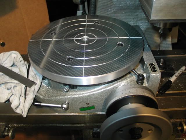
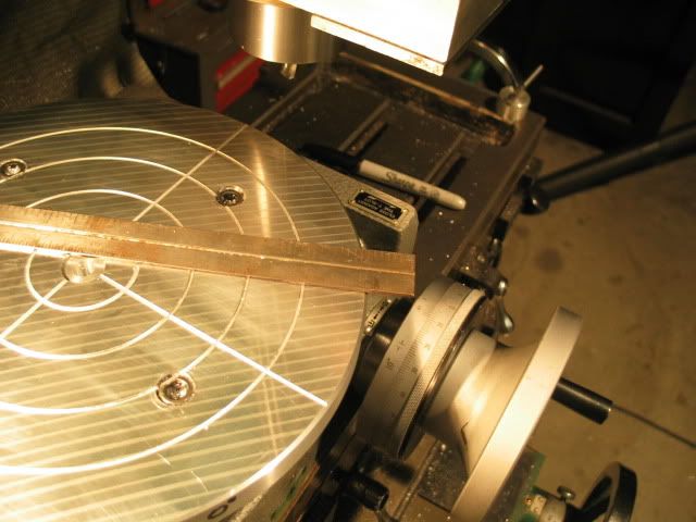
Some pics of the initial lay out . Set the degree wheel on 0º and using a 90º spotting drill cut a line .005" deep , spin the dials 22 times and 2º and cut a perpendicular line . By using the power feed on the x , the lines lay straight with the table . Thought this would help on layout when setting up the piece to be worked on .
0º on the rotab .
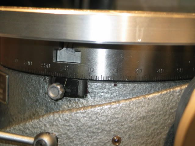
Cut concentric circles on 1" spacing . for centering a part .
Now it's time to do the drilling for the threaded hole for the clamp studs . Haven't come up with a pattern that I like yet . Believe that I better take the plate off of the rotab so I don't drill thru and mark up the table on the rotab .
In retrospect in sizing the OD of the plate , it could have been bigger to utilize the available space without blocking the cranking wheel w/ the degree markings .
Re: Mic-6 jig plate for the new rotab
Posted: Wed Nov 03, 2010 12:08 am
by Harold_V
coal miner wrote: Harold do you think Chinese anticipated the wear ?
Wish I could speak for them, but I don't have a clue. I expect that if they are serious about the work they're turning out, it's at least a concept. Makes a lot of sense to do so.
I'm impressed with your thinking process, and the results you're achieving. All too cool!

Harold