Adapter Project

Topics include, Machine Tools & Tooling, Precision Measuring, Materials and their Properties, Electrical discussions related to machine tools, setups, fixtures and jigs and other general discussion related to amateur machining.

Moderators: GlennW, Harold_V

User avatar
Hawk99
Posts: 190
Joined: Wed Dec 02, 2009 7:04 pm
Location: EDDY, TX

Adapter Project

Post by Hawk99 »

After a few months on the forum, I learn that these are supposed to be posted here instead of in General. I have never been accused of being the sharpest tool in the drawer. I hate to post this project because I make things with semi-precision methods. Someday I hope to have the proper tools. So try to look past how and look at what.

I posted this adapter with questions on the General forum. This is a more step by step.
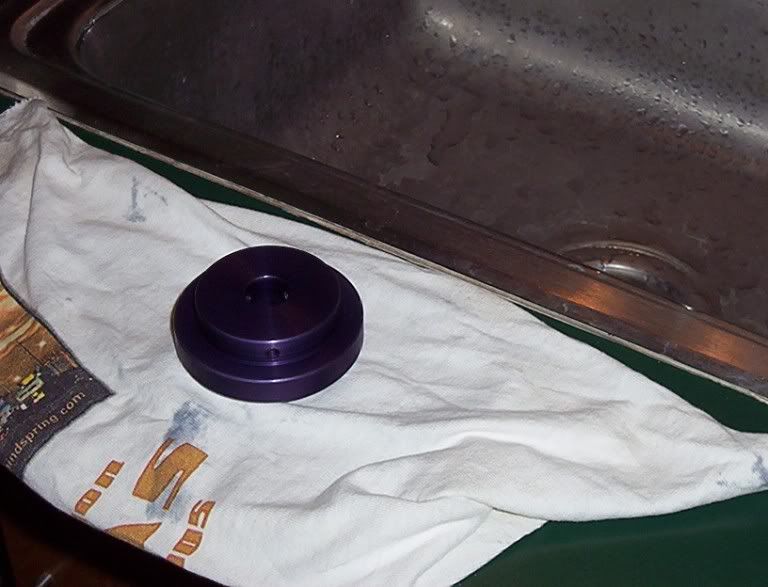
Finished Product
Image

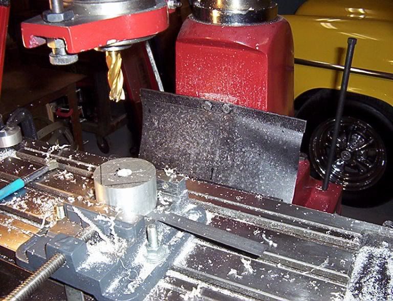
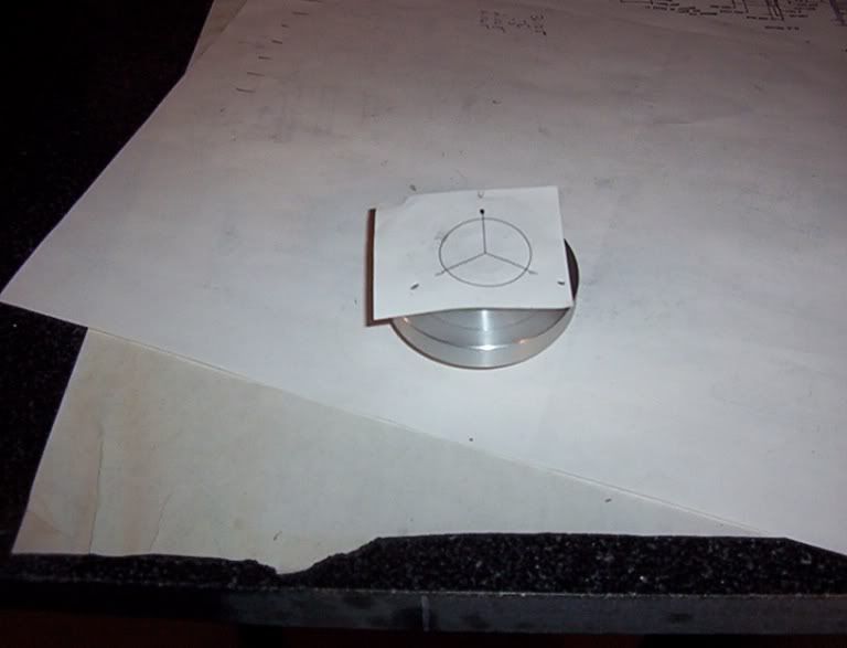
Using a 6061 T6 drop I get from a local plant I drilled a 1/2" hole (3/8" drill then 1/2" end mill). Notice the drill press vise. It took a long time to get it set and it still has the usual problems of a cheap vise. My lathe would not chuck the 2-7/8" piece, so the hole is for a bolt to hold in the chuck to turn the OD to 2-3/4" which my chuck will hold. Notice the two black lines on the part. That is two chords that I did a perpendicular bi-sect to find the center. I did tell you that I do not have the proper tools.
Image

Then I turned two 7/16" shoulders, one to 1.250 OD and the one for the back side to what ever size would allow my tap to tap all the way to the center hole. (Notice the quick change post, homemade also)
Image

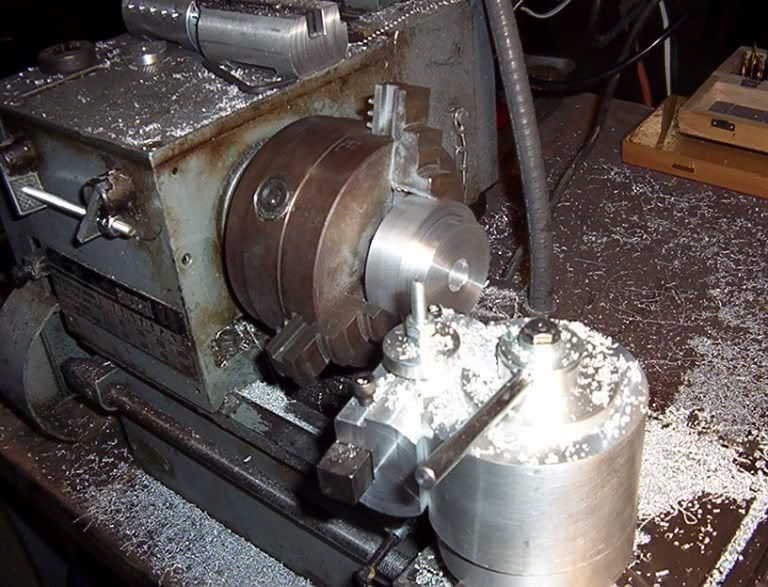
Tested the wheel then drilled the 5/8" hole needed for the shaft size. I did not ream, as the adapter rides on the six spaced set screws.
Image

Then my homemade dividing head by way of AutoCad.
Image

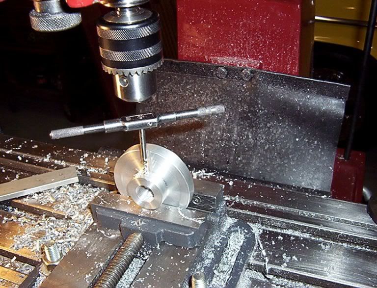
Then I used those dividing head measurements and center drilled, tap drilled and threaded six holes.
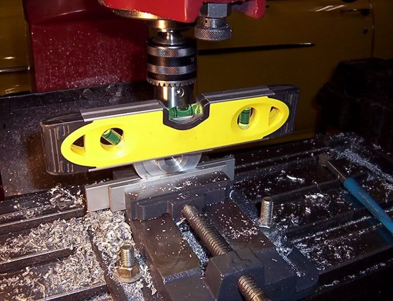
The second pic is finding exact quadrant (center) of piece to drill. Using a small pcs of alum pinned between the center drill and part, placed a level on top and move x axis until level. Same technique as used on a lathe to align cutting tool except horizonal.
Image

Image

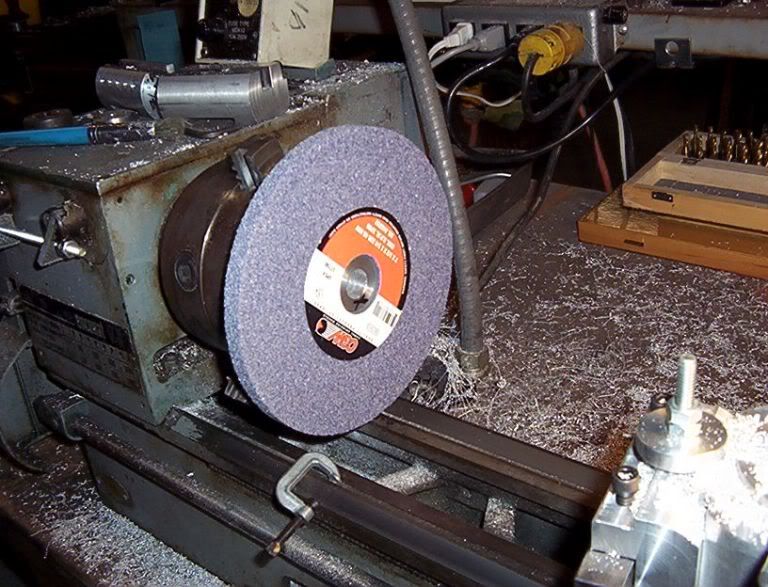
Then using my dial indicator, I adjusted the adapter to run true at the shaft and vertically, mounted the wheel and checked it for true. Used tape to keep the wheel off my indicator. This machine used to vibrate so badly that nothing would stay on the shelf and I had to put my leg against the machine to keep it in place. Now it is so smooth that there is no noise except the motor.

Image

Well that is how it was done. The 1-1/4" shoulder for the wheel was cut to 1.249. Harold's tolerance was 1.250 -.002. I am retrofitting a pedestal stand built in the '50s by my dad. I will post it also when complete. I did modify Harold's drawing to fit my situation.

Frank
SteveM
Posts: 7767
Joined: Mon Jun 27, 2005 6:18 pm
Location: Wisconsin

Post by SteveM »

Hey, don't knock yourself! Nice job with limited resources.

Steve
User avatar
Hawk99
Posts: 190
Joined: Wed Dec 02, 2009 7:04 pm
Location: EDDY, TX

Post by Hawk99 »

Thanks Steve

I call it "work arounds". All of the critical dimensions are within tolerance anyway.

I will someday make them out of steel.

Frank
JackF
Posts: 1617
Joined: Mon Jan 26, 2009 3:56 pm
Location: Caldwell, Idaho

Post by JackF »

Nice work Frank. Did you check the wheel for balance? From your description of the final result it sounds like it may well be balanced.

Jack.
User avatar
coal miner
Posts: 479
Joined: Tue Mar 18, 2008 6:19 pm
Location: Southern Illinios

Post by coal miner »

Looks pretty good to me . If It works and is safe that's all that matters . Some times critical dimensions turn to ctfif [cut to fit in field ]. I have that same grinder , a power house it's not . It works OK for occasional use . It will work w/ a good white rock for roughing tool bits .
The more I learn , The more I don't know !
Jose Rivera
Posts: 3803
Joined: Wed Feb 21, 2007 9:21 pm
Location: Vallejo California

Post by Jose Rivera »

Frank, not really.

This folder is mostly for pictures non related to machining.

Projects and results from member's efforts get more attention o the General.
You'll get more responses and advise there.

Readers may note that the thread has been moved to the General Forum.

Harold
There are no problems, only solutions.
--------------
Retired journeyman machinist and 3D CAD mechanical designer - hobbyist - grandpa
User avatar
Hawk99
Posts: 190
Joined: Wed Dec 02, 2009 7:04 pm
Location: EDDY, TX

Post by Hawk99 »

Thanks Jack and Coal Miner, when I mounted the wheel, I first checked with a dial indicator, then trued it, then dressed it. It became soooo smooth after that. I decided it must be balanced and ready to use. I will pick up the 80 grit soon and set up the other side. Hopefully that wheel will be as smooth.

Jose, I figured that a detailed step by step would go here. I thought I asked question on General

I will eventually get it right.

Frank
User avatar
Bill Shields
Posts: 10594
Joined: Fri Dec 21, 2007 4:57 am
Location: 39.367, -75.765
Contact:

thoughts

Post by Bill Shields »

as a general rule with set screws holding things on shafts:

it isn't always a good idea to put 3 screws in 120 apart as you have.

If you tighten up all three, there is a good chance that you can have the shaft held only by the set screws and not actually up against the metal of the hub.

industrially, the standard way of doing what you intend is 2 set screws 90 degrees apart. This pushes the shaft up against the hub for a positive location.
Lew Hartswick
Posts: 775
Joined: Sat Jan 04, 2003 10:45 am
Location: Albuquerque NM

Re: thoughts

Post by Lew Hartswick »

Bill Shields wrote:as a general rule with set screws holding things on shafts:

it isn't always a good idea to put 3 screws in 120 apart as you have.

If you tighten up all three, there is a good chance that you can have the shaft held only by the set screws and not actually up against the metal of the hub.

industrially, the standard way of doing what you intend is 2 set screws 90 degrees apart. This pushes the shaft up against the hub for a positive location.
I was thinking about that too. I came the conclusion that if the fit is a good
sliding fit one set screw on a flat would be the best BUT if super crit.
balance is the goal then the 3 at 120 deg would be best an maybe some
low force "locktite" (TM) would take care of the clearances. ???????
...lew...
User avatar
Bill Shields
Posts: 10594
Joined: Fri Dec 21, 2007 4:57 am
Location: 39.367, -75.765
Contact:

screws

Post by Bill Shields »

no, the 2 screws is still the best way to go. Used to supervise a shop that did industrial high speed balancing and turbo machinery maintenance..and we never EVER used 3 screws for anything, no matter how 'tight' the fit.

if you are worried about balance, the drill a minor counterbalance 'divit' as needed but do the math...

Considering the mass differential of 2 steel screws vs. the aluminum removed and the diameter on which they are installed, you will never see / feel it in the mass of the other rotating elements.
User avatar
Hawk99
Posts: 190
Joined: Wed Dec 02, 2009 7:04 pm
Location: EDDY, TX

Post by Hawk99 »

Bill and Lew

Well I think maybe you are missing the purpose of this adapter. When I mount a grinding wheel, I do not want a tight fit at the shaft as it might crack or damage the wheel when tightened. This adapter has two purposes. The first is to adapt the center hole from 5/8" to 1-1/4". The second is to be able to adjust the trueness of the wheel on two axis, vertical and horizonal. Once the wheel is running true in both directions, the wheel is captured between an inside and outside flange held in place by a nut. There should be no or almost no load on the set screws.

This special purpose grinder, with the proper wheels, should require minimal pressures when grinding. This machine will only grind HHS tools and drills.

Does any of this make sense now.

Thanks for all the comments.

Frank
User avatar
Harold_V
Posts: 20251
Joined: Fri Dec 20, 2002 11:02 pm
Location: Onalaska, WA USA

Post by Harold_V »

The design is intended to have six screws, with a bore that, in theory, makes no contact with the shaft.

The chance that a machined adapter will run concentric is almost zero otherwise, due to shifting when screws are tightened. That might be fine for a pulley and belt, but not acceptable for a grinding wheel you hope to run on center. The two sets of screws allow for adjustment.

When properly applied, the design works without issues, considering mine was built and put in service back in '67, and has performed flawlessly since.

Harold
Post Reply