
Well I am back at it. Finally getting the head off the bench! Did the tear down, clean up, and painting over the last week or so. Scrounged up some new SKF bearings cheap off of EBAY including 2 universally matched angular contact bearing for the spindle. Putting it back together now. Thought some might want to see the progress / tore down head.
https://www.flickr.com/photos/119635371@N02
https://www.flickr.com/photos/119635371 ... 2246011363
Kao Fong Mill Rebuild, getting this off the work bench!
Re: Kao Fong Mill Rebuild, getting this off the work bench!
Well the progress continues. For the first time ever the new motor for the repowered mill sits in its new home. Seem like the new 2HP looks a little over powering for the Kao Fong!?
https://www.flickr.com/photos/119635371 ... 86/sizes/l
https://www.flickr.com/photos/119635371 ... 86/sizes/l
Re: Kao Fong Mill Rebuild, getting this off the work bench!
Quite the restoration and the pics along the way are really good. It is easy for me to say but I share your concern about the weight of that 2hp. It is extended and that weight at the angles the mill is capable, means you need to watch it.
Fwiw, I've been around a while and seen various heads cracked in their motor housings. The older motors of 1/2- 3/4 hp were heavy things weighing around 52 lbs. The Bridgeport J heads went to Pancake/ flatter motors in 1-2 hp. for reasons and they were a heavier head.
Fwiw, I've been around a while and seen various heads cracked in their motor housings. The older motors of 1/2- 3/4 hp were heavy things weighing around 52 lbs. The Bridgeport J heads went to Pancake/ flatter motors in 1-2 hp. for reasons and they were a heavier head.
Re: Kao Fong Mill Rebuild, getting this off the work bench!
spro wrote:Quite the restoration and the pics along the way are really good. It is easy for me to say but I share your concern about the weight of that 2hp. It is extended and that weight at the angles the mill is capable, means you need to watch it.
Fwiw, I've been around a while and seen various heads cracked in their motor housings. The older motors of 1/2- 3/4 hp were heavy things weighing around 52 lbs. The Bridgeport J heads went to Pancake/ flatter motors in 1-2 hp. for reasons and they were a heavier head.
Agreed, thanks for your input, still pondering this potential concern....
I weighed the original motor and at came out at ~40 pounds. I didn't weight the new motor, but researched others and my new motor should be between 50 and 60 pounds. So a good chuck more that the original. I certainly wouldn't want to crack my housings....that be a bad day for the mill.
I'm not too concerned with the head in the vertical configuration but that certainly gets more stressive as the head is tilted. The other thing I have going is the VFD which I'm certain I can curtail the power out with appropriate settings to curtail stresses on the mill.
Brian
Re: Kao Fong Mill Rebuild, getting this off the work bench!
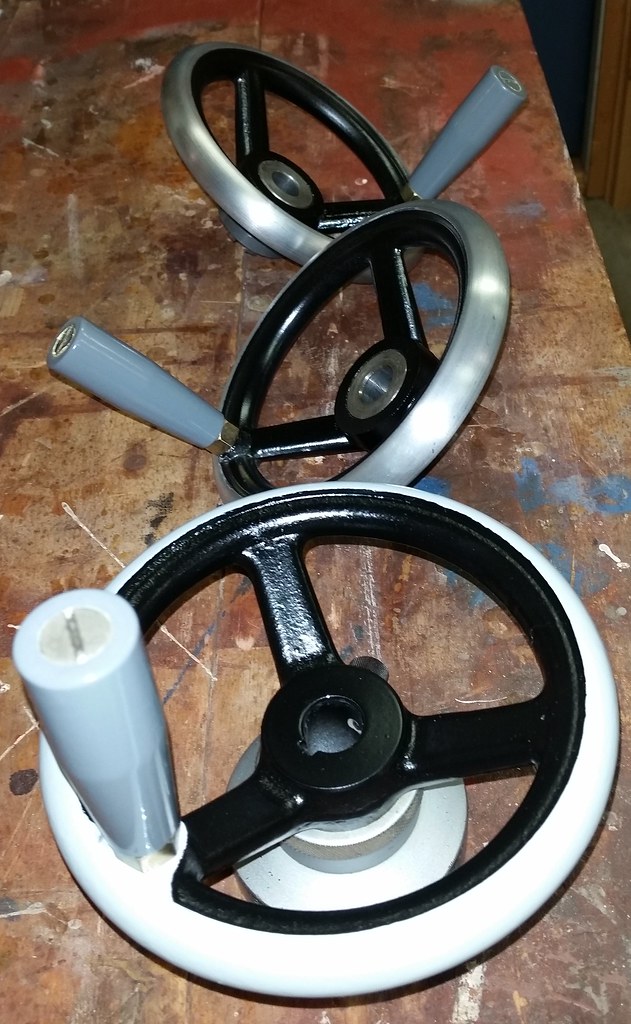
its hand wheel restoration days...

Re: Kao Fong Mill Rebuild, getting this off the work bench!
beautiful job. Thanks for the motivation. I only got about half through my head this past weekend. Had some distractions. Good thing it was shop related. How long have you been into this mill?
Standards are so important that everyone must have their own...
To measure is to know - Lord Kelvin
Disclaimer: I'm just a guy with a few machines...
To measure is to know - Lord Kelvin
Disclaimer: I'm just a guy with a few machines...
Re: Kao Fong Mill Rebuild, getting this off the work bench!
ctwo wrote:beautiful job. Thanks for the motivation. I only got about half through my head this past weekend. Had some distractions. Good thing it was shop related. How long have you been into this mill?
well, lol, have been into it way tooo long, but I'm finally getting it off me bench. With focus and time it really doesn't take too much time relatively speaking, but real life tends to stomp over that! really at this point I'm getting off the bench to make some room for some mopar parts!
Re: Kao Fong Mill Rebuild, getting this off the work bench!
What are mopar parts doing on a cheby work bench? I only put pontiac parts on my bench. 

Jack
Jack
Re: Kao Fong Mill Rebuild, getting this off the work bench!
LOL good eye! Well I'm and old chevy guy with some mopar history if ya can believe that! Anything but a ford! I currently have in the driveway / garage a GoMango Charger 2005, 2011 or so Silverado and a 1968 Plymouth GTX ohh and some Audi A3 nonsence fror the wife. My dad was a chevy dealer....I grew up in that garage.JackF wrote:What are mopar parts doing on a chevy work bench? I only put pontiac parts on my bench.
Jack
BTW my bud has a 68 Judge with a total anal nut and bolt restoration........sweet car.
-
Utah Smitty
- Posts: 10
- Joined: Thu Jan 14, 2016 6:03 pm
Re: Kao Fong Mill Rebuild, getting this off the work bench!
Brian
I am very impressed with the work you've done on this mill--you're obviously a craftsman that takes pride in your work.
I've lurked here off an on for several months, but finally got signed up... the main motivation being my recent acquisition of a South Bend Heavy 10 lathe and, a little earler, a Rutland KF-VAO-AIS vertical mill, which I found is made by Kao Fong. The attached picture shows the mill when I picked it up.
I looked at the photos on the Flicker site and you show another KF/Grizzly? Mill that is appears identical to mine--which is essentially a Grizzly 1004.
The Rutland has a rumble in the spindle so I tore into it this week--I got the end pieces and nuts off the top and bottom of the spindle assy, but got stumped trying to remove the pinion shaft with the handle on it...I did a search here on the site, and Voila' the first item I see is your rebuild of your Kao Fong. Talk about good fortune.
So anyway, is there any trick to removing the pinion shaft that raises and lowers the spindle? I've got the handle off and the outer covers on both sides removed, but I cant get the shaft to move either left or right, even with a little (gentle) persuasion with a rubber mallet.
Any help you could provide would be deeply appreciated. I've committed to a couple of friends to do some work for them that will require the mill, and I hope to have it running this week.
After that, I will be installing a table X-axis feed, and a DRO... but first things first.
Again, thanks for sharing your work with us...
Regards,
Utah Smitty
- Attachments
-
Re: Kao Fong Mill Rebuild, getting this off the work bench!
Well glad I could be helpful!
I do have a number of other mill pictures on the flickr site that I collected that I felt were similar to mine. I only have one mill, the other pictures were captured for me to compare and understand more.
So your quill feed seems to be similar to mine and many others. See the attached photo.
There isn't much holding that pinion in shaft in. You should be able to remove 56, 57, 61, 62, etc and free everything up on the right side.
Then take off 53 and 54 and drive things out to the right with gentle bumps with a hammer. In the process you need to remove 50, 51, 52 and the key.
I have this whole assembly taken apart and photographed. I believe it is on Flickr. If not let me know.
good luck
Brian
- Attachments
-
-
Utah Smitty
- Posts: 10
- Joined: Thu Jan 14, 2016 6:03 pm
Re: Kao Fong Mill Rebuild, getting this off the work bench!
Thanks Brian!rakort wrote:Well glad I could be helpful!
I do have a number of other mill pictures on the flickr site that I collected that I felt were similar to mine. I only have one mill, the other pictures were captured for me to compare and understand more.
So your quill feed seems to be similar to mine and many others. See the attached photo.
There isn't much holding that pinion in shaft in. You should be able to remove 56, 57, 61, 62, etc and free everything up on the right side.
Then take off 53 and 54 and drive things out to the right with gentle bumps with a hammer. In the process you need to remove 50, 51, 52 and the key.
I have this whole assembly taken apart and photographed. I believe it is on Flickr. If not let me know.
god luck
Brian
I looked at the pictures on Flickr, and they helped a lot. Even though your mill is set up more like a Bridgeport, and mine is like the Grizzly in your pictures, the spindle assembly appears to be the same--bearing location, etc.
On my machine 61 and 62 are held in place by a snap ring. I've removed them, and also 53 and 54 on the left side. I've removed the cap screws on 56 and started to move it out, but it feels like the spring is still attached... it will move out a little, then pull back in. I'm going to try and remove 57--I assume it just slides out-- and see if I can work 57 loose of the spring.
When you put them back in, it looks like you need to pre-assemble #55 spring and #56 retainer cap (my terms) to the shaft before sliding the shaft back into the casting.
Also, you said to drive it out to the right, or in other words, the side with the lever... is that correct?
One other question... on my mill, the top bearings are open type, and there wasn't any grease in them. There's a Ditz oiler at the left front of the top--under the pulley cover. It leads to a tube that goes into the bearing housing, but below the first bearing. One of the views in your pictures seems to show a channel that makes a U-turn from the oiler and goes back up above the bearing. It would appear that the bearing is oil lubed by the oil from the oiler, and that the oil falls through the spindle assembly to lube the other 5 bearings there... What is your understanding of this?
Thanks again for your prompt reply and assistance. I promise I won't pester you further... I'm off work tomorrow and I'm going to tackle this thing again...
Regards,
Utah Smitty