Discuss park gauge trains and large scale miniature railways having track gauges from 8" to 24" gauge and designed at scales of 2" to the foot or greater - whether modeled for personal use, or purpose built for amusement park operation or private railroading.
Forum rules
Topics may include: antique park gauge train restoration, preservation, and history; building new grand scale equipment from scratch; large scale miniature railway construction, maintenance, and safe operation; fallen flags; track, gauge, and equipment standards; grand scale vendor offerings; and, compiling an on-line motive power roster.
rkcarguy wrote:I bought 50 pieces of the LED's from amazon so I've got lots, but I'm not sure if I'm sold yet on the brightness of the yellow and red. The green is very bright though.
It didn't used to be that way. When green LEDs first came on the market they were substantially dimmer than red ones.
I may try something different and go with surface mounted LED's.
Why?
———————————————————————————————————————————————————————
Music isn’t at all difficult. All you gotta do is play the right notes at the right time!
The surface mount versions are much brighter, more amp draw though too. No harm in experimenting a bit with different leds.
I think if I came up with a way to secure the "prism" lens within my head, I could mount whatever lights I wanted behind it because they wouldn't be seen anymore, just like the H2 style here:
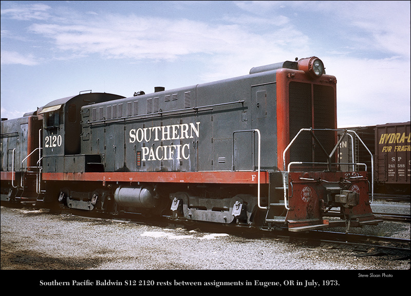
I've always loved the SP paint colors and actually have a bunch of them in HO scale, I'd planned on modeling the cascade route when I got the space to setup my layout again.
Black and Orange ran here when I was a kid, so I'm torn lol
Tonight I attached three pieces of angle to the inside cab end of the locomotive body, aligned the cab to it, and installed some temporary rivets to hold it together in the right place. I'll be installing some screws from inside the cab so it can be separated from the body if needed for repairs or modifications later. Then I cut the opening for the exhaust stack and got about halfway through the opening over the "engine". The S12 has some sort of cover centered on the body forward of the stack over the engine, I'm going to make this cover flip up to access the gas and hydraulic fluid fillers.
Lastly I removed the centrifugal clutch, exhaust, carb, and motor mount(all the go kart stuff) from the 420cc motor and got it cleaned up a bit.
I found a nice close up picture of an S12 last night, and it looks like the front grille was expanded metal. Aluminum expanded metal is made as small as about 3/8x3/16 openings, so I am going to see if I can get my hands on some of that.
This weekend I'm hoping to get the nose put together, and notch/curve two pieces of aluminum angle "furring" strips so I have something to rivet to when I install the rolled top of the cab. Also plan to finish cutting the "engine hatch" hole, rivet some angle around it's opening, and see if I can find a cabinet hinge to correctly fit the cover.
I also made a good find, and found a company selling 20mm, or about 13/16 diameter, reflectors with a clear lens(like the inside of a Maglite), that will work perfect for the two individual headlights that are inside the larger round lens on an S12.
Last edited by rkcarguy on Fri Sep 22, 2017 6:34 pm, edited 1 time in total.
Another question? How heavy do I want this locomotive to be?
Right now I'm looking at:
90#'s Steel angle frame
36#'s rectangle tube "fuel tank"
About 40#'s for the aluminum body
70#'s of fluids.
44# Engine
Trucks are expected to be about 50#'s each
No idea for hydraulic parts, compressor, and alternator.
It's getting close to being time to order/scrounge steel for the frame and I'm wondering if I need to start building things from tube or solid plate haha! The fuel tank is going to be a 15" long piece of 8x6x3/8 square tube...I was planning on making it a big muffler, but could fill it full of something heavy and then make a separate muffler instead.
I got the angle riveted around the one opening, and another opening cut where the grille will go. This one took a long time because this opening is not framed in or covered with something, so I had to scribe lines, cut out the opening close, and then grind/file the opening out to the scribe lines. Then I got some aluminum channel cut and riveted inside the nose to give it some structure before I ran out of evening.
rkcarguy wrote:Another question? How heavy do I want this locomotive to be?
Right now I'm looking at:
90#'s Steel angle frame
36#'s rectangle tube "fuel tank"
About 40#'s for the aluminum body
70#'s of fluids.
44# Engine
Trucks are expected to be about 50#'s each
No idea for hydraulic parts, compressor, and alternator.
It's getting close to being time to order/scrounge steel for the frame and I'm wondering if I need to start building things from tube or solid plate haha! The fuel tank is going to be a 15" long piece of 8x6x3/8 square tube...I was planning on making it a big muffler, but could fill it full of something heavy and then make a separate muffler instead.
RK, similar loco's in smaller gauges e.g. 7 1/2" often run 800 #, occasionally up to 1000 lbs and more with fuel and operator. You will want weight on the drivers to achieve necessary traction.
Glenn
Moderator - Grand Scale Forum
Motive power : 1902 A.S.Campbell 4-4-0 American - 12 5/8" gauge, 1955 Ottaway 4-4-0 American 12" gauge
Ahaha, Retirement: the good life - drifting endlessly on a Sea of projects....
All right thanks Glenn, looks like it's time to start using plate!
The exterior frame rails are going to be steel angle 2-1/2x3-1/2x3/8, then the rectangle tube 8x6x3/8 fuel tank, and some 4" pipe air tanks on each side. The bolster and coupler pocket area is where I'm going to start piling on the plate.
I'll be using 2" or 3" ship channel for most of my engine and car frames. All my trucks are I think 3/8" plate. I can measure when I get home if you wish. Probably up to 1/2" plate would ok for frames but overkill for trucks, (in 12" ga). The double flanges provide great strength but don't extend as far away from the web , so are more to scale. A good rule of thumb when you are trying to sort out what size material to use is estimate the original size structural materials then factor it down according to what scale you are building in. Iam in general building in 1/4 scale, so 2" or say 21/2" channel equates to 8" or 10" channel on the full size prototype. Also, for me, most of the cars Iam interested in were originally built with channel frames. So a very good match on materials and engineering for my preferred designs.
Glenn
Moderator - Grand Scale Forum
Motive power : 1902 A.S.Campbell 4-4-0 American - 12 5/8" gauge, 1955 Ottaway 4-4-0 American 12" gauge
Ahaha, Retirement: the good life - drifting endlessly on a Sea of projects....
I've been trying to do that as well, choose prototypical member sizes that is. My design for my S12 is basically an aluminum upper body, which will remove from the frame, leaving the steps, walkways, fuel tank, air tanks, couplers/bolsters, and frame as one fabrication. The sides of the S12 are thick at the walkway, coming to a 2-3/8" tall dimension in scale. I can't have the 2nd leg of the channel inward as it will interfere with the wheels and truck pivoting.
I have a sketch of some rolling stock truck sides drawn up for the laser cutter, also from 3/8 plate and I agree that's about the right thickness. My trucks look a little odd though, because the 1" flanged bearings I'm using have a rather large housing. They are probably in the line of being more like 1/4 scale instead of 1/6th. I'd like to stick with them though, they are common, cheap, made to the same spec over several manufacturers, and have a massive loading capacity, probably more than my track will take.
For my bulkhead cars, I got some 6" aluminum I-beam remnants years ago that are going to work perfect. I'm planning to cope the web out of each end, and taper them down to 2" with integrated coupler pockets. Just add some ribs extending to each side and the exterior looks of the bulkhead car and I'm set.
Sounds good. These days, the cost of aluminium is way out of my ball park, but it,sounds like you have some stock on hand.
BTW, Mostly the channel iron is turned flange outward, so nothing to interfere with the turning radius of the trucks. Interestingly, the old logging cars often had doubled sticks of channel, bolted, I think, back to back down the center of the cars, for a backbone. One of the cars out at snohomish rail museum is built this way. It looks like it could be dissassembled by hand and any part replaced with common channel, angle iron or flat bar, if need be.
Moderator - Grand Scale Forum
Motive power : 1902 A.S.Campbell 4-4-0 American - 12 5/8" gauge, 1955 Ottaway 4-4-0 American 12" gauge
Ahaha, Retirement: the good life - drifting endlessly on a Sea of projects....
